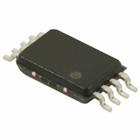
S-35390A-T8T1G Seiko Instruments, S-35390A-T8T1G Datasheet - Page 39

S-35390A-T8T1G
Manufacturer Part Number
S-35390A-T8T1G
Description
IC RTC I2C 2-WIRE 8-TSSOP
Manufacturer
Seiko Instruments
Type
Clock/Calendarr
Datasheet
1.S-35390A-J8T1G.pdf
(56 pages)
Specifications of S-35390A-T8T1G
Time Format
HH:MM:SS (12/24 hr)
Date Format
YY-MM-DD-dd
Interface
I²C, 2-Wire Serial
Voltage - Supply
1.3 V ~ 5.5 V
Operating Temperature
-40°C ~ 85°C
Mounting Type
Surface Mount
Package / Case
8-TSSOP
Function
Clock/Calendar/Alarm/Battery Backup/Interrupt
Supply Voltage (max)
5.5 V
Supply Voltage (min)
1.3 V
Maximum Operating Temperature
+ 85 C
Minimum Operating Temperature
- 40 C
Mounting Style
SMD/SMT
Rtc Bus Interface
Serial (2-Wire, I2C)
Lead Free Status / RoHS Status
Lead free / RoHS Compliant
Memory Size
-
Lead Free Status / Rohs Status
Lead free / RoHS Compliant
Other names
728-1007-2
Available stocks
Company
Part Number
Manufacturer
Quantity
Price
Company:
Part Number:
S-35390A-T8T1G
Manufacturer:
SEIKO
Quantity:
18 700
Part Number:
S-35390A-T8T1G
Manufacturer:
SEIKO
Quantity:
20 000
Rev.3.0
2. Measurement of oscillation frequency
When the S-35390A is turned on, the internal power-on detector operates and a signal of 1 Hz is output from the
pin to select the crystal oscillator and optimize the C
counter following the circuit configuration shown in Figure 51 .
If 1 Hz signal is not output, the power-on detector does not operate normally. Turn off the power and then turn it on
again. For how to apply power, refer to “ Power-on Detection Circuit and Register Status” .
Caution
Remark If the error range is ± 1 ppm in relation to 1 Hz, the time is shifted by approximately 2.6 seconds per month
_00
Open
or pull-up
1 kΩ
(calculated using the following expression).
10
1. Use a high-accuracy frequency counter of 7 digits or more.
2. Measure the oscillation frequency under the usage conditions.
3. Since the 1 Hz signal continues to be output, initialization must be executed during normal
–6
(1 ppm) × 60 seconds × 60 minutes × 24 hours × 30 days = 2.592 seconds
operation.
1 kΩ
Figure 51 Configuration of Oscillation Frequency Measurement Circuit
SDA
SCL
INT2
S-35390A
Seiko Instruments Inc.
g
value. Turn the power on and measure the signal with a frequency
XOUT
INT1
VDD
VSS
XIN
C
2-WIRE REAL-TIME CLOCK
g
10 kΩ
Frequency
counter
S-35390A
INT
39
1


