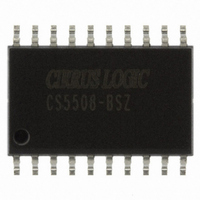
CS5508-BSZ Cirrus Logic Inc, CS5508-BSZ Datasheet - Page 14

CS5508-BSZ
Manufacturer Part Number
CS5508-BSZ
Description
IC ADC 20BIT LOW PWR 20-SOIC
Manufacturer
Cirrus Logic Inc
Datasheet
1.CS5507-ASZ.pdf
(40 pages)
Specifications of CS5508-BSZ
Data Interface
Serial
Number Of Bits
20
Sampling Rate (per Second)
100
Number Of Converters
1
Power Dissipation (max)
4.5mW
Voltage Supply Source
Analog and Digital, Dual ±
Operating Temperature
-40°C ~ 85°C
Mounting Type
Surface Mount
Package / Case
20-SOIC
Resolution (bits)
20bit
Sampling Rate
100SPS
Input Channel Type
Differential
Supply Current
340µA
Digital Ic Case Style
SOIC
No. Of Pins
20
Lead Free Status / RoHS Status
Lead free / RoHS Compliant
Other names
598-1099-5
Available stocks
Company
Part Number
Manufacturer
Quantity
Price
Part Number:
CS5508-BSZ
Manufacturer:
CIRRUS
Quantity:
20 000
14
slope to be used to properly scale the output
digital codes when doing conversions.
The calibration state is entered whenever the
CAL and CONV pins are high at the same time.
The state of the CAL and CONV pins at power-
on and when coming out of sleep are recognized
as commands, but will not be executed until the
end of the 1800 clock cycle wake-up period.
Note that any time CONV transitions from low
to high, the multiplexer inputs A0 and A1 are
latched internal to the CS5505 and CS5506 de-
vices. These latched inputs select the analog
input channel which will be used once conver-
sion commences.
If CAL and CONV become active (high) during
the 1800 clock cycle wake-up time, the con-
verter will wait until the wake-up period elapses
before executing the calibration. If the wake-up
time has elapsed, the converter will be in the
standby mode waiting for instruction and will
enter the calibration cycle immediately. The cali-
bration lasts for 3246 clock cycles. Calibration
coefficients are then retained in the SRAM
(static RAM) for use during conversion.
At the end of the calibration cycle, the on-chip
microcontroller checks the logic state of the
CONV signal. If the CONV input is low the de-
vice will enter the standby mode where it waits
for further instruction. If the CONV signal is
high at the end of the calibration cycle, the con-
verter will enter the conversion state and
perform a conversion on the input channel which
was selected when CONV transitioned from low
to high. The CAL signal can be returned low
any time after calibration is initiated. CONV can
also be returned low, but it should never be
taken low and then taken back high until the
calibration period has ended and the converter is
in the standby state. If CONV is taken low and
then high again with CAL high while the con-
verter is calibrating, the device will interrupt the
current calibration cycle and start a new one. If
CAL is taken low and CONV is taken low and
14
then high during calibration, the calibration cy-
cle will continue as the conversion command is
disregarded. The states of A0, A1 and BP/UP
are not important during calibrations.
If an "end of calibration" signal is desired, pulse
the CAL signal high while leaving the CONV
signal high continuously. Once the calibration is
completed, a conversion will be performed. At
the end of the conversion, DRDY will fall to in-
dicate the first valid conversion after the
calibration has been completed.
See Understanding Converter Calibration for de-
tails on how the converter calibrates its transfer
function.
Conversion
The conversion state can be entered at the end of
the calibration cycle, or whenever the converter
is idle in the standby mode. If CONV is taken
high to initiate a calibration cycle ( CAL also
high), and remains high until the calibration cy-
cle is completed (CAL is taken low after CONV
transitions high), the converter will begin a con-
version upon completion of the calibration
period. The device will perform a conversion on
the input channel selected by the A0 and A1 in-
puts when CONV transitioned high. Table 1
indicates the multiplexer channel selection truth
table for A0 and A1.
The A0 and A1 inputs are latched internal to the
4-channel devices (CS5505/6) when CONV
rises. A0 and A1 have internal pull-down cir-
cuits which default the multiplexer to channel
A1
0
0
1
1
Table 1. Multiplexer Truth Table
A0
0
1
0
1
Channel addressed
CS5505/6/7/8
CS5505/6/7/8
AIN1
AIN2
AIN3
AIN4
DS59F7
DS59F4


