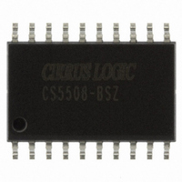
CS5508-BSZ Cirrus Logic Inc, CS5508-BSZ Datasheet - Page 28

CS5508-BSZ
Manufacturer Part Number
CS5508-BSZ
Description
IC ADC 20BIT LOW PWR 20-SOIC
Manufacturer
Cirrus Logic Inc
Datasheet
1.CS5507-ASZ.pdf
(40 pages)
Specifications of CS5508-BSZ
Data Interface
Serial
Number Of Bits
20
Sampling Rate (per Second)
100
Number Of Converters
1
Power Dissipation (max)
4.5mW
Voltage Supply Source
Analog and Digital, Dual ±
Operating Temperature
-40°C ~ 85°C
Mounting Type
Surface Mount
Package / Case
20-SOIC
Resolution (bits)
20bit
Sampling Rate
100SPS
Input Channel Type
Differential
Supply Current
340µA
Digital Ic Case Style
SOIC
No. Of Pins
20
Lead Free Status / RoHS Status
Lead free / RoHS Compliant
Other names
598-1099-5
Available stocks
Company
Part Number
Manufacturer
Quantity
Price
Part Number:
CS5508-BSZ
Manufacturer:
CIRRUS
Quantity:
20 000
28
Control Input Pins
CAL - Calibrate, Pin 3 (4).
CONV - Convert, Pin 2 (3).
A0, A1 - Multiplexer Selection Inputs, Pins (1, 24).
BP/UP - Bipolar/Unipolar, Pin 7 (8).
Measurement and Reference Inputs
AIN+, AIN-, (AIN1+, AIN2+, AIN3+, AIN4+, AIN-) - Differential Analog Inputs, Pins 8, 10 (9,
10, 12, 13, 11).
VREF+, VREF- - Differential Voltage Reference Inputs, Pins 11, 12 (14, 15).
Voltage Reference
VREFOUT - Voltage Reference Output, Pin 13 (16).
Power Supply Connections
VA+ - Positive Analog Power, Pin 14 (17).
VA- - Negative Analog Power, Pin 15 (18).
28
When taken high the same time that the CONV pin is taken high the converter will perform a
self-calibration which includes calibration of the offset and gain scale factors in the converter.
The CONV pin initiates a calibration cycle if it is taken from low to high while the CAL pin is
high, or it initiates a conversion if it is taken from low to high with the CAL pin low. CONV
latches the multiplexer selection when it transitions from low to high on the multiple channel
devices. If CONV is held high (CAL low) the converter will do continuous conversions.
A0 and A1 select the input channel for conversion on the multi-channel input devices. A0 and
A1 are latched when CONV transitions from low to high. These two inputs have pull-down
resistors internal to the chip.
The BP/UP pin selects the conversion mode of the converter. When high the converter will
convert bipolar input signals; when low it will convert unipolar input signals.
AIN- in the CS5505/6 is a common measurement node for AIN1+, AIN2+, AIN3+ and AIN4+.
A differential voltage reference on these pins operates as the voltage reference for the
converter. The voltage between these pins can be any voltage between 1.0 and 3.6 volts.
The on-chip voltage reference is output from this pin. The voltage reference has a nominal
magnitude of 2.5 volts and is referenced to the VA+ pin on the converter.
Positive analog supply voltage. Nominally +5 volts.
Negative analog supply voltage. Nominally -5 volts when using dual polarity supplies; or 0
volts (tied to system analog ground) when using single supply operation.
CS5505/6/7/8
CS5505/6/7/8
DS59F7
DS59F4


