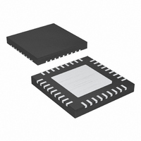
MAX1020BETX+ Maxim Integrated Products, MAX1020BETX+ Datasheet - Page 17

MAX1020BETX+
Manufacturer Part Number
MAX1020BETX+
Description
IC ADC/DAC 10BIT 36-TQFN-EP
Manufacturer
Maxim Integrated Products
Type
ADC, DACr
Datasheet
1.MAX1020BETX.pdf
(44 pages)
Specifications of MAX1020BETX+
Resolution (bits)
10 b
Sampling Rate (per Second)
225k
Data Interface
MICROWIRE™, QSPI™, Serial, SPI™
Voltage Supply Source
Analog and Digital
Voltage - Supply
4.75 V ~ 5.25 V
Operating Temperature
-40°C ~ 85°C
Mounting Type
Surface Mount
Package / Case
36-TQFN Exposed Pad
Lead Free Status / RoHS Status
Lead free / RoHS Compliant
MAX1020
27–31, 34
26
35
36
—
—
—
—
—
—
—
—
—
—
10-Bit, Multichannel ADCs/DACs with FIFO,
MAX1022
33, 34, 35
23, 25,
27–31,
26
—
—
—
36
—
—
—
—
—
—
—
1
______________________________________________________________________________________
MAX1057/
MAX1058
2, 3, 5, 6
Temperature Sensing, and GPIO Ports
16, 17,
33, 34,
20, 21
29–32
36–47
35
—
—
—
—
—
—
48
—
1
GPIOA0–GPIOA3 Gener al - P ur p ose I/O A0–A3. GP IOA0–GP IOA3 can si nk and sour ce 15m A.
GPIOB0–GPIOB3
GP IOC 0–GP IOC 3
CNVST/AIN11
CNVST/AIN15
CNVST/AIN7
REF2/AIN10
AIN0–AIN13
REF2/AIN14
AIN0–AIN5
REF2/AIN6
AIN0–AIN9
NAME
REF1
EP
Reference 1 Input. Reference voltage; leave unconnected to use the
internal reference (2.5V for the MAX1057 or 4.096V for the
MAX1020/MAX1022/MAX1058). REF1 is the positive reference in ADC
external differential reference mode. Bypass REF1 to AGND with a 0.1µF
capacitor in external reference mode only. See the ADC/DAC References
section.
Analog Inputs
Reference 2 Input/Analog-Input Channel 6. See Table 5 for details on
programming the setup register. REF2 is the negative reference in the
ADC external differential reference.
Active-Low Conversion-Start Input/Analog Input 7. See Table 5 for details
on programming the setup register.
Active-Low Conversion-Start Input/Analog Input 11. See Table 5 for
details on programming the setup register.
Analog Inputs
Reference 2 Input/Analog-Input Channel 10. See Table 5 for details on
programming the setup register. REF2 is the negative reference in the
ADC external differential reference.
Active-Low Conversion-Start Input/Analog Input 15. See Table 5 for
details on programming the setup register.
General-Purpose I/O B0–B3. GPIOB0–GPIOB3 can sink 4mA and
source 2mA.
General-Purpose I/O C0–C3. GPIOC0–GPIOC3 can sink 4mA and
source 2mA.
Analog Inputs
Reference 2 Input/Analog-Input Channel 14. See Table 5 for details on
programming the setup register. REF2 is the negative reference in the
ADC external differential reference.
Exposed Paddle. Must be externally connected to AGND. Do not use as
a ground connect.
Pin Description (continued)
FUNCTION
17


