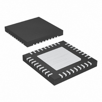
MAX1020BETX+ Maxim Integrated Products, MAX1020BETX+ Datasheet - Page 30

MAX1020BETX+
Manufacturer Part Number
MAX1020BETX+
Description
IC ADC/DAC 10BIT 36-TQFN-EP
Manufacturer
Maxim Integrated Products
Type
ADC, DACr
Datasheet
1.MAX1020BETX.pdf
(44 pages)
Specifications of MAX1020BETX+
Resolution (bits)
10 b
Sampling Rate (per Second)
225k
Data Interface
MICROWIRE™, QSPI™, Serial, SPI™
Voltage Supply Source
Analog and Digital
Voltage - Supply
4.75 V ~ 5.25 V
Operating Temperature
-40°C ~ 85°C
Mounting Type
Surface Mount
Package / Case
36-TQFN Exposed Pad
Lead Free Status / RoHS Status
Lead free / RoHS Compliant
10-Bit, Multichannel ADCs/DACs with FIFO,
Temperature Sensing, and GPIO Ports
CS rising edge. All GPIOs default to inputs upon power-
up.
The data in the register controls the function of each
GPIO, as shown in Tables 13–19.
Table 13. MAX1020 GPIO Configuration
Table 14. MAX1057/MAX1058 GPIO Configuration
Table 15. MAX1020 GPIO Write
Table 16. MAX1057/MAX1058 GPIO Write
30
DIN
DOUT
DIN
DOUT
DIN
DOUT
DIN
DOUT
DATA PIN
DATA PIN
DATA PIN
DATA PIN
______________________________________________________________________________________
0
0
0
0
0
0
0
0
0
0
0
0
GPIO COMMAND BYTE
GPIO COMMAND BYTE
0
0
0
0
GPIO COMMAND BYTE
0
0
GPIO COMMAND BYTE
0
0
0
0
0
0
0
0
0
0
0
0
0
0
0
0
0
0
0
0
0
0
0
0
0
0
0
0
1
0
1
0
0
0
1
0
0
0
1
0
1
0
0
0
1
0
0
0
0
0
GPIOC1
GPIOC1
0
0
0
DATA BYTE 1
DATA BYTE 1
0
0
0
Write the command byte 00000010 to indicate a GPIO
write operation. The eight SCLK cycles following the
command byte load data from DIN into the GPIO write
register in the MAX1020. The 16 SCLK cycles following
the command byte load data from DIN into the GPIO
write register in the MAX1057/MAX1058. See Tables 15
and 16. The register bits are updated after the last CS
rising edge.
GPIOC0
0
0
GPIOC0
0
0
0
0
0
0
GPIOA1
GPIOA1
DATA BYTE
0
0
DATA BYTE
0
0
0
0
GPIOA0
0
0
GPIOA0
0
0
0
0
DATA BYTE 2
DATA BYTE 2
0
0
X
0
X
0
X
0
X
0
X
0
X
0
GPIO Write
X
X
0
0
X
0
X
0
X
0
X
0
X
0
0
X
0
X
0
X


