ISL90842UIV1427Z-TK Intersil, ISL90842UIV1427Z-TK Datasheet - Page 8

ISL90842UIV1427Z-TK
Manufacturer Part Number
ISL90842UIV1427Z-TK
Description
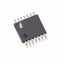
IC POT DGTL QUAD 50K OHM 14TSSOP
Manufacturer
Intersil
Series
XDCP™r
Datasheet
1.ISL90842WIV1427Z-TK.pdf
(10 pages)
Specifications of ISL90842UIV1427Z-TK
Taps
256
Resistance (ohms)
50K
Number Of Circuits
4
Temperature Coefficient
45 ppm/°C Typical
Memory Type
Volatile
Interface
I²C, 2-Wire Serial
Voltage - Supply
2.7 V ~ 5.5 V
Operating Temperature
-40°C ~ 85°C
Mounting Type
Surface Mount
Package / Case
14-TSSOP
Resistance In Ohms
50K
Lead Free Status / RoHS Status
Lead free / RoHS Compliant
Other names
ISL90842UIV1427Z-TKTR
The ISL90842 responds with an ACK after recognition of a
START condition followed by a valid Identification Byte, and
once again after successful receipt of an Address Byte. The
ISL90842 also responds with an ACK after receiving a Data
Byte of a write operation. The master must respond with an
ACK after receiving a Data Byte of a read operation
A valid Identification Byte contains 01010 as the five MSBs,
and the following two bits matching the logic values present
at pins A1 and A0. The LSB is the Read/Write bit. Its value is
SDA OUTPUT FROM
SDA OUTPUT FROM
TRANSMITTER
SCL FROM
RECEIVER
SDA
SCL
MASTER
SIGNALS FROM
SIGNAL AT SDA
SIGNALS FROM
THE MASTER
THE ISL90842
8
START
FIGURE 9. VALID DATA CHANGES, START, AND STOP CONDITIONS
START
FIGURE 10. ACKNOWLEDGE RESPONSE FROM RECEIVER
HIGH IMPEDANCE
S
A
R
T
T
0
FIGURE 11. BYTE WRITE SEQUENCE
IDENTIFICATION
1
1
0
BYTE
1
STABLE
0
DATA
A1
ISL90842
A0
WRITE
0
A
C
K
CHANGE
DATA
0 0 0 0
ADDRESS
“1” for a Read operation, and “0” for a Write operation (See
Table 1).
(MSB)
BYTE
0 0 0 0
0
STABLE
DATA
TABLE 1. IDENTIFICATION BYTE FORMAT
1
A
C
K
8
Logic values at pins A1, and A0 respectively
0
DATA
BYTE
1
HIGH IMPEDANCE
STOP
ACK
9
0
A
C
K
S
T
O
P
A1
A0
January 16, 2006
FN8096.1
(LSB)
R/W


