ATS627LSGTN-T Allegro Microsystems Inc, ATS627LSGTN-T Datasheet
ATS627LSGTN-T
Specifications of ATS627LSGTN-T


Related parts for ATS627LSGTN-T


ATS627LSGTN-T Summary of contents
Page 1
Features and Benefits • Highly accurate in presence of: ▫ Anomalous target geometry (tooth-tooth variation) ▫ Signature teeth or valleys ▫ Target runout • Highly repeatable output edges (low jitter) • True zero-speed operation • Undervoltage lockout • Air gap ...
Page 2
... ATS627LSG Selection Guide Part Number ATS627LSGTN-T 800 pieces per 13-in. reel ® *Contact Allegro for additional packing options Absolute Maximum Ratings Characteristic Supply Voltage Output Off Voltage Reverse Supply Voltage Reverse Output Voltage Output Current Operating Ambient Temperature Maximum Junction Temperature ...
Page 3
ATS627LSG OPERATING CHARACTERISTICS Reference Target 60+2; unless otherwise specified Characteristics Electrical Characteristics Supply Voltage 2 Undervoltage Lockout Reverse Supply Current 3 Supply Zener Clamp Voltage Supply Current Test Pin Zener Clamp Voltage 4 Power-On Characteristics Power-On State Output Stage Characteristics ...
Page 4
ATS627LSG OPERATING CHARACTERISTICS Reference Target 60+2; unless otherwise specified Characteristics Performance Characteristics (continued) Relative Timing Accuracy, Sequential Mechanical Falling Edges Relative Timing Accuracy, Signature ERR Mechanical Rising Edge Relative Timing Accuracy, Signature ERR Mechanical Falling Edge Relative Repeatability, Sequential Rising ...
Page 5
ATS627LSG Figure 1. Definition of Output Delay Time, t Target V = the processed analog signal of the sinusoidal magnetic input (per channel) PROC T = period between successive sensed target mechanical edges of the same TARGET Figure 2. Definition ...
Page 6
ATS627LSG Supply Current (On) versus Supply Voltage Supply Voltage, V Supply Current (Off) versus Supply Voltage Supply Voltage, ...
Page 7
ATS627LSG 360° Repeatability versus Air Gap Sequential Region, 3 Rising Edges at Each T 0.30 0.25 0.20 0.15 0.10 Specification Limit 0. 0.5 1.0 1.5 2.0 Air Gap, AG (mm) True Zero Speed, Low Jitter, High Accuracy Output ...
Page 8
ATS627LSG Signature Feature, Rising Edge 1.5 1.0 0.5 0 -0.5 -1.0 -1.5 0 500 1000 1500 Operational Speed, S Sequential Features, Rising Edge 1.5 1.0 0.5 0 -0.5 -1.0 -1.5 0 500 1000 1500 Operational Speed, S True Zero Speed, ...
Page 9
ATS627LSG Signature Feature, Rising Edge 1.5 1.0 0.5 0 -0.5 -1.0 -1.5 0 500 1000 1500 Operational Speed, S Sequential Features, Rising Edge 1.5 1.0 0.5 0 -0.5 -1.0 -1.5 0 500 1000 1500 Operational Speed, S True Zero Speed, ...
Page 10
ATS627LSG Signature Feature, Rising Edge 1.5 1.0 0.5 0 -0.5 -1.0 -1.5 0 0.5 1.0 1.5 Air Gap, AG (rpm) Sequential Features, Rising Edge 1.5 1.0 0.5 0 -0.5 -1.0 -1.5 0 0.5 1.0 1.5 Air Gap, AG (rpm) True ...
Page 11
ATS627LSG Signature Feature, Rising Edge 1.5 1.0 0.5 0 -0.5 -1.0 -1.5 -50 - Ambient Temperature, T Sequential Features, Rising Edge 1.5 1.0 0.5 0 -0.5 -1.0 -1.5 -50 - Ambient Temperature, ...
Page 12
ATS627LSG Signature Feature, Rising Edge 1.5 1.0 0.5 0 -0.5 -1.0 -1.5 -50 - Ambient Temperature, T Sequential Features, Rising Edge 1.5 1.0 0.5 0 -0.5 -1.0 -1.5 -50 - Ambient Temperature, ...
Page 13
ATS627LSG Signature Feature, Rising Edge 1.5 1.0 0.5 0 -0.5 -1.0 -1.5 0 500 1000 1500 Operational Speed, S Sequential Features, Rising Edge 1.5 1.0 0.5 0 -0.5 -1.0 -1.5 0 500 1000 1500 Operational Speed, S True Zero Speed, ...
Page 14
ATS627LSG may require derating at maximum conditions, see Power Derating section Thermal Characteristics Characteristic Package Thermal Resistance *Additional thermal information available on the Allegro website 1900 1800 1700 1600 1500 1400 1300 1200 1100 1000 900 800 700 600 500 ...
Page 15
ATS627LSG Reference Target 60+2 Characteristics Symbol Outside Diameter D Outside diameter of target o Breadth of tooth, with respect to Face Width F branded face Length of tooth, with respect to Angular Tooth Thickness t branded face; measured at D ...
Page 16
ATS627LSG Sensing Technology The ATS627 contains a single-chip differential Hall-effect sensor IC, a samarium cobalt pellet, and a flat ferrous pole piece (con- centrator). As shown in figure 5, the Hall IC supports two Hall elements, which sense the magnetic ...
Page 17
ATS627LSG Undervoltage Lockout When the supply voltage falls below the undervoltage lockout voltage the device enters Reset, where the output CC(UV) state returns to the Power-On State (POS) until sufficient V is supplied. This lockout feature prevents false ...
Page 18
ATS627LSG PDAC Tracking Figure 8. Operation of Bounded Update method (for illustrative purposes only, values may not be to scale) • Two DACs track the V peaks. • The DACs track the V and Np values are used to establish ...
Page 19
ATS627LSG Power Derating The device must be operated below the maximum junction tem- perature of the device, T (max). Under certain combinations of J peak conditions, reliable operation may require derating supplied power or improving the heat dissipation properties of ...
Page 20
ATS627LSG Typical Application 0.1 μF (Recommended) Figure 9. Basic typical application circuit True Zero Speed, Low Jitter, High Accuracy 1 VCC BYPASS ATS627 3 TEST VOUT GND 4 Position Sensor Output 2 ...
Page 21
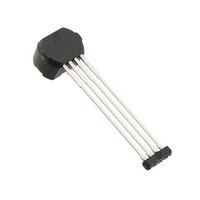
ATS627LSG 1.10 F 8.00±0.05 5.80±0.05 E1 1.70±0.10 4.70±0. 24.65±0.10 15.30±0.10 A 5.50±0.10 True Zero Speed, Low Jitter, High Accuracy Package SG, 4-Pin SIP 5.50±0.05 1. Branded E2 Face A 4 0.71±0.05 0.60±0.10 0.40±0.10 1.0 REF ...
Page 22
ATS627LSG Revision History Revision Rev. 1 Copyright ©2011, Allegro MicroSystems, Inc. Allegro MicroSystems, Inc. reserves the right to make, from time to time, such de par tures from the detail spec tions as may be required to ...