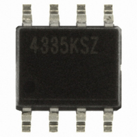
CS4335-KSZ Cirrus Logic Inc, CS4335-KSZ Datasheet

CS4335-KSZ
Specifications of CS4335-KSZ
Available stocks
Related parts for CS4335-KSZ
CS4335-KSZ Summary of contents
Page 1
Stereo D/A Converter Features Complete Stereo DAC System: Interpolation, D/A, Output Analog Filtering 24-Bit Conversion 96 dB Dynamic Range -88 dB THD+N Low Clock-Jitter Sensitivity Single +5 V Power Supply Filtered Line-Level Outputs On-Chip Digital De-emphasis ...
Page 2
... Internal Serial Clock Generation ............................................................................................. 11 Figure 8. System Block Diagram............................................................................................................. 12 Figure 9. De-Emphasis Curve (Fs = 44.1kHz) ........................................................................................ 14 Figure 10. CS4334 Data Format (I²S) ....................................................................................................... 15 Figure 11. CS4335 Data Format ............................................................................................................... 15 Figure 12. CS4338 Data Format ............................................................................................................... 16 Figure 13. CS4339 Data Format ............................................................................................................... 16 Figure 14. CS4334/5/8/9 Initialization and Power-Down Sequence ......................................................... 17 Figure 15. Stopband Rejection.................................................................................................................. 18 Figure 16. Transition Band........................................................................................................................ 18 Figure 17 ...
Page 3
Figure 18. Passband Ripple...................................................................................................................... 18 Figure 19. Stopband Rejection.................................................................................................................. 19 Figure 20. Transition Band........................................................................................................................ 19 Figure 21. Transition Band........................................................................................................................ 19 Figure 22. Passband Ripple...................................................................................................................... 19 Figure 23. 0 dBFS FFT (BRM) .................................................................................................................. 20 Figure 24. -60 dBFS FFT (BRM).............................................................................................................. 20 ...
Page 4
... DEM /SCLK Processor 3 LRCK 4 External Clock MCLK Figure 1. Recommended Connection Diagram 4 Confidential Draft 3/11/08 + 0.1 µF 1 µ 3.3 µF 8 AOUTL + Ω 267 CS4334 CS4335 CS4338 CS4339 3.3 µF 5 AOUTR + Ω 267 CS4334/5/8/9 +5V Ω 560 Left Audio Output Ω Ω 560 Right Audio ...
Page 5
CHARACTERISTICS AND SPECIFICATIONS (All Min/Max characteristics and specifications are guaranteed over the Specified Operating Conditions. Typical performance characteristics and specifications are derived from measurements taken at nominal supply voltages and T = 25°C.) A SPECIFIED OPERATING CONDITIONS (AGND = ...
Page 6
ANALOG CHARACTERISTICS (Full-Scale Output Sine Wave, 997 Hz; Test load R 48 kHz, Measurement Bandwidth kHz, unless otherwise specified; Fs for High-Rate Mode = 96 kHz, Measurement Bandwidth kHz, unless otherwise specified.) ...
Page 7
ANALOG CHARACTERISTICS Parameter Combined Digital and On-chip Analog Filter Response Passband to -0.05 dB corner to -0.1 dB corner corner Frequency Response kHz Passband Ripple StopBand StopBand Attenuation Group Delay Passband Group Delay ...
Page 8
POWER AND THERMAL CHARACTERISTICS Parameters Power Supplies Power Supply Current Power Dissipation Package Thermal Resistance Power Supply Rejection Ratio Notes: 7. Refer to Figure 4. Max Power Dissipation is measured at VA=5.5V. AGND 8 Confidential Draft 3/11/08 Symbol Min normal ...
Page 9
Safe Operating 50 Region 25 2 Resistive Load -- R Figure 3. Maximum Loading DIGITAL INPUT CHARACTERISTICS Parameters High-Level Input Voltage Low-Level Input Voltage Input Leakage Current Input Capacitance Notes for CS433X ...
Page 10
SWITCHING CHARACTERISTICS Parameters Input Sample Rate MCLK Pulse Width High MCLK Pulse Width Low MCLK Pulse Width High MCLK / LRCK = 384 or 192 MCLK Pulse Width Low MCLK / LRCK = 384 or 192 MCLK Pulse Width High ...
Page 11
LRCK SCLK SDATA Figure 5. External Serial Mode Input Timing * Figure 6. Internal Serial Mode Input Timing The SCLK pulses shown are internal to ...
Page 12
GENERAL DESCRIPTION The CS4334 family of devices offers a complete stereo digital-to-analog system including digital interpolation, fourth-order delta-sigma digital-to-analog conversion, digital de-emphasis and analog filtering, as shown in Figure 8. This architecture provides a high tolerance to clock jitter. ...
Page 13
SYSTEM DESIGN The CS4334 family accepts data at standard audio sample rates including 48, 44.1 and 32 kHz in BRM and 96, 88.2 and 64 kHz in HRM. Audio data is input via the serial data input pin (SDATA). ...
Page 14
De-Emphasis The CS4334 family includes on-chip digital de-emphasis. equal to 44.1 kHz. The frequency response of the de-emphasis curve will scale proportionally with changes in sample rate, Fs. The de-emphasis filter is active (inactive) if the DEM/SCLK pin is ...
Page 15
... LSB MSB - I² 24-Bit Data Data Valid on Rising Edge of SCLK Figure 10. CS4334 Data Format (I² Left Justified 24-Bit Data Data Valid on Rising Edge of SCLK Figure 11. CS4335 Data Format CS4334/5/8/9 Figures nel + LSB External SCLK Mode nel +5 +4 ...
Page 16
clocks Internal SCLK Mode Right Justified, 16-Bit Data INT SCLK = ...
Page 17
Figure 14. CS4334/5/8/9 Initialization and Power-Down Sequence DS248F5 Confidential Draft 3/11/08 CS4334/5/8/9 17 ...
Page 18
Overall Base-Rate Frequency Response Figure 15. Stopband Rejection Figure 17. Transition Band 18 Confidential Draft 3/11/08 Figure 16. Transition Band Figure 18. Passband Ripple CS4334/5/8/9 DS248F5 ...
Page 19
Overall High-Rate Frequency Response Figure 19. Stopband Rejection Figure 21. Transition Band DS248F5 Confidential Draft 3/11/08 Figure 20. Transition Band Figure 22. Passband Ripple CS4334/5/8/9 19 ...
Page 20
Base Rate Mode Performance Plots + -10 -10 -10 -20 -20 -20 -30 -30 -30 -40 -40 -40 -50 -50 -50 -60 -60 - -70 -70 r -70 A -80 -80 -80 -90 -90 ...
Page 21
High Rate Mode Performance Plots + -10 -10 -10 -20 -20 -20 -30 -30 -30 -40 -40 -40 -50 -50 -50 -60 -60 - -70 -70 - -80 -80 -80 -90 -90 ...
Page 22
PARAMETER DEFINITIONS Total Harmonic Distortion + Noise (THD+N) The ratio of the rms value of the signal to the rms sum of all other spectral components over the specified bandwidth (typically 10Hz to 20kHz), including distortion components. Expressed in ...
Page 23
PACKAGE DIMENSIONS 8L SOIC (150 MIL BODY) PACKAGE DRAWING 1 b SEATING PLANE e DIM ∝ DS248F5 Confidential Draft 3/11/ INCHES MIN MAX 0.053 ...
Page 24
... ORDERING INFORMATION Model Temperature CS4334-KSZ -10 to +70 °C CS4335-KSZ -10 to +70 °C CS4338-KSZ -10 to +70 °C CS4339-KSZ -10 to +70 °C CS4334-DSZ -40 to +85 °C CS4335-DSZ -40 to +85 °C CS4338-DSZ -40 to +85 °C CS4339-DSZ -40 to +85 °C 9. FUNCTIONAL COMPATIBILITY CS4330-KS ⇒ CS4339-KSZ CS4331-KS ⇒ CS4334-KSZ CS4333-KS ⇒ CS4338-KSZ CS4330-BS ⇒ CS4339-DSZ CS4331-BS ⇒ ...


