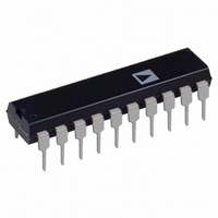
DAC312HPZ Analog Devices Inc, DAC312HPZ Datasheet - Page 13

DAC312HPZ
Manufacturer Part Number
DAC312HPZ
Description
IC DAC 12BIT HS MULT 20-DIP
Manufacturer
Analog Devices Inc
Datasheet
1.DAC312HPZ.pdf
(14 pages)
Specifications of DAC312HPZ
Data Interface
Parallel
Settling Time
250ns
Number Of Bits
12
Number Of Converters
1
Voltage Supply Source
Dual ±
Power Dissipation (max)
375mW
Operating Temperature
-40°C ~ 85°C
Mounting Type
Through Hole
Package / Case
20-DIP (0.300", 7.62mm)
Resolution (bits)
12bit
Input Channel Type
Parallel
Supply Current
-13.9mA
Digital Ic Case Style
DIP
No. Of Pins
20
Operating Temperature Range
-40°C To +85°C
Number Of Channels
1
Resolution
12b
Interface Type
Parallel
Single Supply Voltage (typ)
Not RequiredV
Dual Supply Voltage (typ)
±15V
Architecture
R-2R
Power Supply Requirement
Dual
Output Type
Current
Integral Nonlinearity Error
±0.05LSB
Single Supply Voltage (min)
Not RequiredV
Single Supply Voltage (max)
Not RequiredV
Dual Supply Voltage (min)
-10.8/4.5V
Dual Supply Voltage (max)
±18V
Operating Temp Range
-40C to 85C
Operating Temperature Classification
Industrial
Mounting
Through Hole
Pin Count
20
Package Type
PDIP N
Lead Free Status / RoHS Status
Lead free / RoHS Compliant
Lead Free Status / RoHS Status
Lead free / RoHS Compliant, Lead free / RoHS Compliant
Available stocks
Company
Part Number
Manufacturer
Quantity
Price
Company:
Part Number:
DAC312HPZ
Manufacturer:
LT
Quantity:
1 200
DAC312
DESCRIPTION OF OPERATION
The DAC312 is divided into two major sections, an 8 segment
generator and a 9-bit master/slave D/A converter. In operation
the device performs as follows (see Simplified Schematic).
The three most significant bits (MSBs) are inputs to a 3-to-8
line decoder. The selected resistor (R5 in the figure) is con-
nected to the master/slave 9-bit D/A converter. All lower order
resistors (R1 through R4) are summed into the I
line, while all
O
higher order resistors (R6 through R8) are summed into the I
O
line. The R5 current supplies 512 steps of current (0 mA to
0.499 mA for a 1 mA reference current) which are also summed
into the I
or I
lines depending on the bits selected. In the fig-
O
O
ure, the code selected is: 100 110000000. Therefore, 2 mA (4
0.5 mA/segment) +0.375 mA (from master/slave D/A converter)
are summed into I
giving an I
of 2.375 mA. I
has a current
O
O
O
of 1.625 mA with this code. As the three MSB’s are increment-
ed, each successively higher code adds 0.5 mA to I
and sub-
Expanded Transfer Characteristic Segment (001 010 011)
O
tracts 0.5 mA from I
, with the selected resistor feeding its
O
current to the master/slave D/A converter; thus each increment
of the 3 MSBs allows the current in the 9-bit D/A converter to
be added to a pedestal consisting of the sum of all lower order
currents from the segment generator. This configuration guar-
antees monotonicity.
Simplified Schematic
REV. C
–13–


