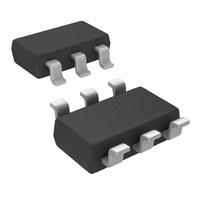
DAC121S101CIMK/NOPB National Semiconductor, DAC121S101CIMK/NOPB Datasheet - Page 18

DAC121S101CIMK/NOPB
Manufacturer Part Number
DAC121S101CIMK/NOPB
Description
CONV D/A 12BIT MICRO PWR TSOT236
Manufacturer
National Semiconductor
Series
PowerWise®r
Datasheet
1.DAC121S101CIMKNOPB.pdf
(20 pages)
Specifications of DAC121S101CIMK/NOPB
Settling Time
12µs
Number Of Bits
12
Data Interface
DSP, MICROWIRE™, QSPI™, Serial, SPI™
Number Of Converters
1
Voltage Supply Source
Single Supply
Power Dissipation (max)
1.72mW
Operating Temperature
-40°C ~ 105°C
Mounting Type
Surface Mount
Package / Case
TSOT-23-6, TSOT-6
Number Of Channels
1
Resolution
12b
Interface Type
Serial (3-Wire, SPI, QSPI, Microwire)
Single Supply Voltage (typ)
3.3/5V
Dual Supply Voltage (typ)
Not RequiredV
Architecture
Resistor-String
Power Supply Requirement
Single
Output Type
Voltage
Integral Nonlinearity Error
±8LSB
Single Supply Voltage (min)
2.7V
Single Supply Voltage (max)
5.5V
Dual Supply Voltage (min)
Not RequiredV
Dual Supply Voltage (max)
Not RequiredV
Operating Temp Range
-40C to 105C
Operating Temperature Classification
Industrial
Mounting
Surface Mount
Pin Count
6
Package Type
TSOT
For Use With
DAC121S101EVAL - BOARD EVALUATION DAC121S101
Lead Free Status / RoHS Status
Lead free / RoHS Compliant
Other names
DAC121S101CIMK
DAC121S101CIMKTR
DAC121S101CIMKTR
Available stocks
Company
Part Number
Manufacturer
Quantity
Price
Company:
Part Number:
DAC121S101CIMK/NOPB
Manufacturer:
MICROCHIP
Quantity:
1 001
Part Number:
DAC121S101CIMK/NOPB
Manufacturer:
TI/德州仪器
Quantity:
20 000
www.national.com
The output voltage of this circuit for any code is found to be
where D is the input code in decimal form. With VA = 5V and
R1 = R2,
A list of rail-to-rail amplifiers suitable for this application are
indicated in
2.4 LAYOUT, GROUNDING, AND BYPASSING
For best accuracy and minimum noise, the printed circuit
board containing the DAC121S101 should have separate
analog and digital areas. The areas are defined by the loca-
V
O
LMC7111
LM7301
LM8261
= (V
AMP
TABLE 2. Some Rail-to-Rail Amplifiers
A
x (D / 4096) x ((R1 + R2) / R1) - V
Table
V
2.
O
SOT23-5
SOT23-5
SOT23-5
= (10 x D / 4096) - 5V
PKGS
DIP-8
SO-8
Typ V
0.03 mV
0.9 mV
0.7 mV
OS
A
Typ I
x R2 / R1)
620 µA
25 µA
1 mA
SUPPLY
18
tions of the analog and digital power planes. Both of these
planes should be located in the same board layer. There
should be a single ground plane. A single ground plane is
preferred if digital return current does not flow through the
analog ground area. Frequently a single ground plane design
will utilize a "fencing" technique to prevent the mixing of ana-
log and digital ground current. Separate ground planes should
only be utilized when the fencing technique is inadequate.
The separate ground planes must be connected in one place,
preferably near the DAC121S101. Special care is required to
guarantee that digital signals with fast edge rates do not pass
over split ground planes. They must always have a continu-
ous return path below their traces.
The DAC121S101 power supply should be bypassed with a
10µF and a 0.1µF capacitor as close as possible to the device
with the 0.1µF right at the device supply pin. The 10µF ca-
pacitor should be a tantalum type and the 0.1µF capacitor
should be a low ESL, low ESR type. The power supply for the
DAC121S101 should only be used for analog circuits.
Avoid crossover of analog and digital signals and keep the
clock and data lines on the component side of the board. The
clock and data lines should have controlled impedances.


