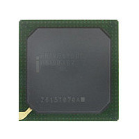
PRIXP425BC 869083 Intel, PRIXP425BC 869083 Datasheet - Page 44

PRIXP425BC 869083
Manufacturer Part Number
PRIXP425BC 869083
Description
Manufacturer
Intel
Datasheet
1.PRIXP425BC_869083.pdf
(130 pages)
Specifications of PRIXP425BC 869083
Core Operating Frequency
400MHz
Package Type
BGA
Pin Count
492
Mounting
Surface Mount
Operating Temperature (max)
70C
Operating Temperature (min)
0C
Operating Temperature Classification
Commercial
Lead Free Status / Rohs Status
Compliant
- Current page: 44 of 130
- Download datasheet (3Mb)
Table 13.
Intel
Datasheet
44
®
IXP42X Product Line of Network Processors and IXC1100 Control Plane Processor
Expansion Bus Interface
EX_CLK
EX_ALE
EX_ADDR[23:0]
EX_WR_N
EX_RD_N
EX_CS_N[7:0]
EX_DATA[15:0]
EX_IOWAIT_N
EX_RDY[3:0]
†
††
Name
For a legend of the Type codes, see
For new designs, this signal should be pulled high with a 10-KΩ resistor when not being utilized in the
system. No change is required to existing designs that have this signal pulled low.
Power
or Sys
Reset
Reset
Z
Z
H
Z
Z
Z
Z
H
H
Reset
Post
H
H
H
Z
0
1
1
1
0
Intel
Type
I/O
I/O
O
O
O
O
I
I
I
®
†
IXP42X product line and IXC1100 control plane processors
Table 5 on page
Input clock signal used to sample all expansion interface
inputs and clock all expansion interface outputs.
Address-latch enable used for multiplexed address/data bus
accesses. Used in Intel and Motorola* multiplexed modes of
operation.
Expansion-bus address used as an output for data accesses
over the expansion bus. Also, used as an input during reset to
capture device configuration. These signals have a weak pull-
up resistor attached internally. Based on the desired
configuration, various address signals must be pulled low in
order for the device to operate in the desired mode.
Intel-mode write strobe / Motorola-mode data strobe
(EXP_MOT_DS_N) / TI*-mode data strobe (TI_HDS1_N).
Intel-mode read strobe / Motorola-mode read-not-write
(EXPB_MOT_RNW) / TI mode read-not-write (TI_HR_W_N).
External chip selects for expansion bus.
Expansion-bus, bidirectional data
Data ready/acknowledge from expansion-bus devices.
Expansion-bus access is halted when an external device sets
EX_IOWAIT_N to logic 0 and resume from the halted location
once the external device sets EX_IOWAIT_N to logic 1. This
signal affects accesses that use EX_CS_N[7:0] when the chip
select is configured in Intel- or Motorola-mode of operation.
Should be pulled high through a 10-KΩ resistor when not
being utilized in the system.
HPI interface ready signals. Can be configured to be active
high or active low. These signals are used to halt accesses
using Chip Selects 7 through 4 when the chip selects are
configured to operate in HPI mode. There is one RDY signal
per chip select. This signal only affects accesses that use
EX_CS_N[7:4].
Should be pulled high
being utilized in the system.
• Chip selects 0 through 7 can be configured to support
• Chip selects 4 through 7 can be configured to support TI
Intel or Motorola bus cycles.
HPI bus cycles.
33.
††
though a 10-KΩ resistor when not
Description
Document Number: 252479-006US
August 2006
Related parts for PRIXP425BC 869083
Image
Part Number
Description
Manufacturer
Datasheet
Request
R

Part Number:
Description:
IC NETWRK PROCESSR 400MHZ 492BGA
Manufacturer:
Intel
Datasheet:

Part Number:
Description:
Microprocessor: Intel Celeron M Processor 320 and Ultra Low Voltage Intel Celeron M Processor at 600MHz
Manufacturer:
Intel Corporation

Part Number:
Description:
Intel 82550 Fast Ethernet Multifunction PCI/CardBus Controller
Manufacturer:
Intel Corporation
Datasheet:

Part Number:
Description:
Intel StrataFlash memory 32 Mbit. Access speed 120 ns
Manufacturer:
Intel Corporation
Datasheet:

Part Number:
Description:
Intel StrataFlash memory 32 Mbit. Access speed 120 ns
Manufacturer:
Intel Corporation
Datasheet:

Part Number:
Description:
Intel StrataFlash memory 64 Mbit. Access speed 150 ns
Manufacturer:
Intel Corporation
Datasheet:

Part Number:
Description:
Intel StrataFlash memory 32 Mbit. Access speed 100 ns
Manufacturer:
Intel Corporation
Datasheet:

Part Number:
Description:
DA28F640J5A-1505 Volt Intel StrataFlash Memory
Manufacturer:
Intel Corporation
Datasheet:

Part Number:
Description:
5 Volt Intel StrataFlash?? Memory
Manufacturer:
Intel Corporation
Datasheet:

Part Number:
Description:
5 Volt Intel StrataFlash?? Memory
Manufacturer:
Intel Corporation

Part Number:
Description:
Intel 6300ESB I/O Controller Hub
Manufacturer:
Intel Corporation
Datasheet:

Part Number:
Description:
Intel 82801DB I/O Controller Hub (ICH4), Pb-Free SLI
Manufacturer:
Intel Corporation
Datasheet:

Part Number:
Description:
Intel 82801FB I/O Controller Hub (ICH6)
Manufacturer:
Intel Corporation
Datasheet:

Part Number:
Description:
Intel Strataflash Memory28F128J3 28F640J3 28F320J3
Manufacturer:
Intel Corporation
Datasheet:


