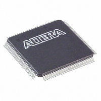
EPF6016ATC100-3 Altera, EPF6016ATC100-3 Datasheet - Page 30

EPF6016ATC100-3
Manufacturer Part Number
EPF6016ATC100-3
Description
IC FLEX 6000 FPGA 16K 100-TQFP
Manufacturer
Altera
Series
FLEX 6000r
Datasheet
1.EPF6010ATC100-3N.pdf
(52 pages)
Specifications of EPF6016ATC100-3
Number Of Logic Elements/cells
1320
Number Of Labs/clbs
132
Number Of I /o
81
Number Of Gates
16000
Voltage - Supply
3 V ~ 3.6 V
Mounting Type
Surface Mount
Operating Temperature
0°C ~ 85°C
Package / Case
100-TQFP, 100-VQFP
Family Name
FLEX 6000
Number Of Usable Gates
16000
Number Of Logic Blocks/elements
1320
# Registers
1320
# I/os (max)
81
Frequency (max)
142.86MHz
Process Technology
SRAM
Operating Supply Voltage (typ)
3.3V
Logic Cells
1320
Device System Gates
16000
Operating Supply Voltage (min)
3V
Operating Supply Voltage (max)
3.6V
Operating Temp Range
0C to 85C
Operating Temperature Classification
Commercial
Mounting
Surface Mount
Pin Count
100
Package Type
TQFP
Lead Free Status / RoHS Status
Contains lead / RoHS non-compliant
Total Ram Bits
-
Lead Free Status / Rohs Status
Not Compliant
Other names
544-1274
Available stocks
Company
Part Number
Manufacturer
Quantity
Price
Part Number:
EPF6016ATC100-3
Manufacturer:
ALTERA/阿尔特拉
Quantity:
20 000
Company:
Part Number:
EPF6016ATC100-3N
Manufacturer:
ALTERA
Quantity:
5 510
Company:
Part Number:
EPF6016ATC100-3N
Manufacturer:
ALTERA
Quantity:
1 200
FLEX 6000 Programmable Logic Device Family Data Sheet
Generic Testing
30
Each FLEX 6000 device is functionally tested. Complete testing of each
configurable SRAM bit and all logic functionality ensures 100%
configuration yield. AC test measurements for FLEX 6000 devices are
made under conditions equivalent to those shown in
test patterns can be used to configure devices during all stages of the
production flow.
Figure 17. AC Test Conditions
Symbol
Table 10. JTAG Timing Parameters & Values
t
t
t
t
t
t
t
t
t
t
t
t
t
JCP
JCH
JCL
JPSU
JPH
JPCO
JPZX
JPXZ
JSSU
JSH
JSCO
JSZX
JSXZ
Power supply transients can affect
AC measurements. Simultaneous
transitions of multiple outputs
should be avoided for accurate
measurement. Threshold tests must
not be performed under AC conditions.
Large-amplitude, fast-ground-current
transients normally occur as the
device outputs discharge the load
capacitances. When these transients
flow through the parasitic
inductance between the device
ground pin and the test system ground,
significant reductions in observable
noise immunity can result. Numbers
without parentheses are for 5.0-V
devices or outputs. Numbers in
parentheses are for 3.3-V devices or
outputs. Numbers in brackets are for
2.5-V devices or outputs.
TCK clock period
TCK clock high time
TCK clock low time
JTAG port setup time
JTAG port hold time
JTAG port clock-to-output
JTAG port high impedance to valid output
JTAG port valid output to high impedance
Capture register setup time
Capture register hold time
Update register clock-to-output
Update register high impedance to valid
output
Update register valid output to high
impedance
Parameter
Device
Output
Device input
rise and fall
times < 3 ns
(8.06 kΩ)
(703 Ω)
[521 Ω]
[481 Ω]
464 Ω
250 Ω
Min
100
50
50
20
45
20
45
Figure
Altera Corporation
C1 (includes
JIG capacitance)
Max
25
25
25
35
35
35
17. Multiple
To Test
System
Unit
ns
ns
ns
ns
ns
ns
ns
ns
ns
ns
ns
ns
ns
VCC


