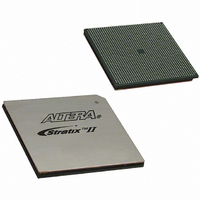
EP2S90F1508I4 Altera, EP2S90F1508I4 Datasheet - Page 132

EP2S90F1508I4
Manufacturer Part Number
EP2S90F1508I4
Description
IC STRATIX II FPGA 90K 1508-FBGA
Manufacturer
Altera
Series
Stratix® IIr
Datasheet
1.EP2S15F484I4N.pdf
(238 pages)
Specifications of EP2S90F1508I4
Number Of Logic Elements/cells
90960
Number Of Labs/clbs
4548
Total Ram Bits
4520488
Number Of I /o
902
Voltage - Supply
1.15 V ~ 1.25 V
Mounting Type
Surface Mount
Operating Temperature
-40°C ~ 100°C
Package / Case
1508-FBGA
Lead Free Status / RoHS Status
Contains lead / RoHS non-compliant
Number Of Gates
-
Other names
544-1923
EP2S90F1508I4
EP2S90F1508I4
Available stocks
Company
Part Number
Manufacturer
Quantity
Price
Company:
Part Number:
EP2S90F1508I4
Manufacturer:
ALTERA
Quantity:
3 000
Company:
Part Number:
EP2S90F1508I4N
Manufacturer:
ALTERA
Quantity:
586
Stratix II Hot-Socketing Specifications
4–2
Stratix II Device Handbook, Volume 1
Devices Can Be Driven Before Power-Up
You can drive signals into the I/O pins, dedicated input pins and
dedicated clock pins of Stratix II devices before or during power-up or
power-down without damaging the device. Stratix II devices support any
power-up or power-down sequence (V
to simplify system level design.
I/O Pins Remain Tri-Stated During Power-Up
A device that does not support hot-socketing may interrupt system
operation or cause contention by driving out before or during power-up.
In a hot socketing situation, Stratix II device's output buffers are turned
off during system power-up or power-down. Stratix II device also does
not drive out until the device is configured and has attained proper
operating conditions.
Signal Pins Do Not Drive the V
Supplies
Devices that do not support hot-socketing can short power supplies
together when powered-up through the device signal pins. This irregular
power-up can damage both the driving and driven devices and can
disrupt card power-up.
Stratix II devices do not have a current path from I/O pins, dedicated
input pins, or dedicated clock pins to the V
before or during power-up. A Stratix II device may be inserted into (or
removed from) a powered-up system board without damaging or
interfering with system-board operation. When hot-socketing, Stratix II
devices may have a minimal effect on the signal integrity of the
backplane.
1
■
■
The hot socketing DC specification is: | I
The hot socketing AC specification is: | I
less.
You can power up or power down the V
pins in any sequence. The power supply ramp rates can range
from 100 μs to 100 ms. All V
within 100 ms of each other to prevent I/O pins from driving
out. During hot socketing, the I/O pin capacitance is less than 15
pF and the clock pin capacitance is less than 20 pF. Stratix II
devices meet the following hot socketing specification.
CCIO
CC
, V
CCIO
supplies must power down
CCINT
, V
CCIO
IOPIN
IOPIN
CCINT
or V
, V
CCIO
CCINT
, and V
| < 300 μA.
| < 8 mA for 10 ns or
CCPD
, V
Altera Corporation
, or V
CCINT
Power
CCPD
CCPD
, and V
) in order
May 2007
pins
CCPD


