20-101-0404 Rabbit Semiconductor, 20-101-0404 Datasheet
20-101-0404
Specifications of 20-101-0404


Related parts for 20-101-0404


20-101-0404 Summary of contents
Page 1
... RabbitCore RCM2000 C-Programmable Module User’s Manual 019–0077 • 090417–K ...
Page 2
... Digi International reserves the right to make changes and improvements to its products without providing notice. Rabbit and Dynamic C are registered trademarks of Digi International Inc. Rabbit 2000 and RabbitCore are trademarks of Digi International Inc. The latest revision of this manual is available on the Rabbit Web site, www.rabbit.com, for free, unregistered download. ...
Page 3
... Chapter 1. Introduction 1.1 Features .................................................................................................................................................1 1.2 Advantages of Using the RCM2000 .....................................................................................................2 1.3 Development and Evaluation Tools......................................................................................................3 1.3.1 Development Kit ...........................................................................................................................3 1.3.2 Development Kit Contents............................................................................................................3 1.3.3 Development Software..................................................................................................................3 1.4 How to Use This Manual ......................................................................................................................4 1.4.1 Additional Product Information ....................................................................................................4 1.4.2 Online Documentation ..................................................................................................................4 Chapter 2. Hardware Setup 2.1 Connections ..........................................................................................................................................6 2 ...
Page 4
... Upgrading Dynamic C ....................................................................................................................... 40 5.4.1 Extras.......................................................................................................................................... 40 Appendix A. Specifications A.1 Electrical and Mechanical Specifications.......................................................................................... 42 A.1.1 Headers ...................................................................................................................................... 45 A.2 Bus Loading ...................................................................................................................................... 46 A.3 Rabbit 2000 DC Characteristics ........................................................................................................ 48 A.4 I/O Buffer Sourcing and Sinking Limit............................................................................................. 49 A.5 Conformal Coating ............................................................................................................................ 50 A.6 Jumper Configurations ...................................................................................................................... 51 Appendix B. Prototyping Board B.1 Overview of the Prototyping Board................................................................................................... 54 B ...
Page 5
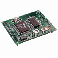
... RAM. Two 40-pin headers bring out the Rabbit 2000 I/O bus, address lines, data lines, parallel ports, and serial ports. The RCM2000 receives its +5 V power from the user board on which it is mounted. The RCM2000 can interface will all kinds of digital devices through the user board. ...
Page 6
... RCM2000 with 18.432 MHz clock and 128K SRAM 1.2 Advantages of Using the RCM2000 • Fast design time for your project since the basic core has already been designed and built. • Competitive pricing compared with purchasing and assembling the individual compo- nents. • ...
Page 7
... Development and Evaluation Tools 1.3.1 Development Kit A complete Development Kit, including a Prototyping Board and Dynamic C develop- ment software, is available for the RCM2000. The Development Kit puts together the essentials you need to design an embedded microprocessor-based system rapidly and efficiently. 1.3.2 Development Kit Contents The RCM2000 Development Kit contains the following items: • ...
Page 8
... How to Use This Manual This user’s manual is intended to give users detailed information on the RCM2000 mod- ule. It does not contain detailed information on the Dynamic C development environment. 1.4.1 Additional Product Information In addition to the product-specific information contained in the RabbitCore RCM2000 User’s Manual (this manual), several higher level reference manuals are provided in HTML and PDF form on the accompanying CD-ROM ...
Page 9
... Prototyping Board. NOTE: This chapter (and this manual) assume that you have the RabbitCore RCM2000 Development Kit. If you purchased an RCM2000 module by itself, you will have to adapt the information in this chapter and elsewhere to your test and development setup. User’s Manual 2 ...
Page 10
... J1 and J3 on the Prototyping Board. Figure 1. Attaching RCM2000 to Prototyping Board NOTE important that you line up the pins on the RCM2000 headers J1 and J2 exactly with the corresponding pins of header sockets J1 and J3 on the Prototyping Board. The header pins may become bent or damaged if the pin alignment is offset, and the RCM2000 will not work ...
Page 11
... Connect RCM2000 to PC Connect the 10-pin connector of the programming cable labeled RCM2000 module as shown in Figure 2 below. Be sure to orient the red edge of the cable towards pin 1 of the connector. (Do not use the serial connection.) Figure 2. RCM2000 Power and Programming Connections NOTE: Some PCs now come equipped only with a USB port. It may be possible to use an RS-232/USB converter (Part No ...
Page 12
... Development kits sold outside North America before 2009 included a header connector that could be connected to 3-pin header J5 on the Prototyping Board. The red and black wires from the connector could then be connected to the positive and negative connections on your power supply. The power supply should deliver 8 V– RabbitCore RCM2000 ...
Page 13
... Check that the RCM2000 is powered correctly — Board should be lit when the RCM2000 is mounted on the Prototyping Board and the AC . adapter is plugged in • Check both ends of the programming cable to ensure that they are firmly plugged into the PC and the connector, not the PROG ming port on the RCM2000 with the marked (colored) edge of the programming cable towards pin 1 of the programming header ...
Page 14
... Dynamic C installation folder. default.htm docs 3. For advanced development topics, refer to the Dynamic C User’s Manual, also in the online documentation set. 2.3.1 Technical Support NOTE: If you purchased your RCM2000 through a distributor or through a Rabbit partner, contact the distributor or partner first for technical support. ...
Page 15
... NOTE assumed in this section that you have at least an elementary grasp of ANSI C. If you do not, see the introductory pages of the Dynamic C User’s Manual for a sug- gested reading list. Each sample program has comments that describe the purpose and function of the program. ...
Page 16
... Prototyping Board should start flashing if everything went well. If this doesn’t work review the following points. • The target should be ready, which is indicated by the message “BIOS successfully com- piled...” If you did not receive this message or you get a communication error, recom- pile the BIOS by typing < ...
Page 17
... LED lights whenever power is connected.) • The programming cable must be connected to the RCM2000. (The colored wire on the programming cable is closest to pin 1 on header J3 on the RCM2000, as shown in Figure 2.) The other end of the programming cable must be connected to the PC serial port ...
Page 18
... Summary of Features So far you have practiced using the following features of Dynamic C. • Loading, compiling and running a program. When you load a program it appears in an edit window. You can compile by selecting menu. When you compile the program compiled into machine language and pile downloaded to the target over the serial port ...
Page 19
... This will cause the program to break if the execution thread hits your break point. • Watch expressions. A watch expression expression that is evaluated on command in the watch window. An expression is basically any type of C formula that can include operators, variables and function calls, but not statements that require multiple lines such as for or switch ...
Page 20
... This program also illustrates a use for a shadow register. A shadow register is used to keep track of the contents of an I/O port that is write only—it can’t be read back. If every time a write is made to the port the same bits are set in the shadow register, then the shadow reg- ister has the same data as the port register ...
Page 21
... It might seem that the biggest problem would be response time because of the big loop time becoming long as the program grows. Our solution for that is called slicing, which is further described in the Dynamic C User’s Manual. User’s Manual 17 ...
Page 22
... The Dynamic C cate if writes and reads did not occur Connect an external SRAM as shown below before you run this sample program. —repeatedly flashes LED DS3 on the Prototyping Board on and off. • FLASHLED.C LED DS3 is controlled by Parallel Port A bit 1 (PA1). ...
Page 23
... DS2 and DS3 on the Prototyping Board on and off. LEDs DS2 and DS3 are controlled by Parallel Port A bit 0 (PA0) and Parallel Port A bit 1 (PA1).Once you have compile this program and it is running, LEDs DS2 and DS3 will flash on/off at different rates. —demonstrates a simple setup for a 2 × 6 keypad and a 2 × 20 LCD. • KEYLCD.C Connect the keypad to Parallel Ports B, C, and D. PB0— ...
Page 24
... LCD that uses the HD44780 con- • LCD_DEMO.C troller or an equivalent. Connect the LCD to the RCM2000 address and data lines on the Prototyping Board. D0—DB0 D1—DB1 D2—DB2 D3—DB3 D4—DB4 D5—DB5 D6—DB6 D7—DB7 A0—RS (Register Select command data) A1—R/W (0=write, 1=read) *— ...
Page 25
... CORE_PARITY.C sending byte values 0–127 from Serial Port B to Serial Port C. The program will switch between generating parity or not on Serial Port B. Serial Port C will always be checking parity, so parity errors should occur during every other sequence. ...
Page 26
... RabbitCore RCM2000 ...
Page 27
... Chapter 4 describes the principal subsystems for the RCM2000. 4.1 RCM2000 Digital Inputs and Outputs Figure 4 shows the subsystems designed into the RCM2000. User’s Manual 4. H ARDWARE Figure 4. Rabbit Subsystems R EFERENCE 23 ...
Page 28
... The RCM2000 has 40 parallel I/O lines grouped in five 8-bit ports available on headers J1 and J2. The 24 bidirectional I/O lines are located on pins PA0–PA7, PD0-PD7, and PE0- PE7. The pinouts for headers J1 and J2 are shown in Figure 5. 24 Figure 5. RCM2000 Pinout RabbitCore RCM2000 ...
Page 29
... The ports on the Rabbit 2000 microprocessor used in the RCM2000 are configurable, and so the factory defaults can be reconfigured. Table 2 lists the Rabbit 2000 factory defaults and the alternate configurations. Table 2. RCM2000 Pinout Configurations Pin Pin Name 1, 20 GND 2 VCC 3–10 PA[0:7] Parallel I/O ...
Page 30
... Table 2. RCM2000 Pinout Configurations (continued) Pin Pin Name 1–13 A[12:0] Output 14 STAT Output (Status) 15 PC0 Output 16 PC1 Input 17 PC2 Output 18 PC3 Input 19 PC4 Output 20 PC5 Input 21 PC6 Output 22 PC7 Input 21 PC6 Output 22 PC7 Input 23–26 PD[0:3] Bitwise or parallel 27 PD4 programmable I/O, can be ...
Page 31
... As shown in Table 2, pins PA0–PA7 can be used to allow the Rabbit 2000 slave to another processor. PE0, PE1, PE4, and PE5 can be used as external interrupts INT0A, INT1A, INT0B, and INT1B. Pins PB0 and PB1 can be used to access the clock on Serial Port B and Serial Port A of the Rabbit microprocessor. Pins PD4 and PD6 can be pro- grammed to be optional serial outputs for Serial Ports B and A ...
Page 32
... Dynamic C v 7.02 and later. This reduces radiated emissions. The primary function of PCLK peripheral clock or a peripheral clock ÷ 2, but PCLK can instead be used as a digital output. See Section 5.2.1, “PCLK Output,” for more informa- tion. Two status mode pins, SMODE0 and SMODE1, are available as inputs. The logic state of these two pins determines the startup procedure after a reset ...
Page 33
... It can be driven low during an interrupt acknowledge cycle can also serve as a general-purpose output. The /RESET_IN pin is an external input that is used to reset the Rabbit 2000 and the onboard peripheral circuits on the RabbitCore module. The serial programming port can be used to force a hard reset on the RabbitCore module by asserting the /RESET_IN signal. ...
Page 34
... The RCM2000 is automatically in Program Mode when the programming cable is attached to the RCM2000, and is automatically in Run Mode when no programming cable is attached. When the Rabbit 2000 is reset, the operating mode is determined by the status of the SMODE pins. When the programming cable’s connector is attached, the SMODE pins are pulled high, placing the Rabbit 2000 in the Program Mode. When the programming cable’ ...
Page 35
... CAUTION: Power to the Prototyping Board or other boards should be disconnected when removing or installing your RCM2000 module to protect against inadvertent shorts across the pins or damage to the RCM2000 if the pins are not plugged in correctly. Do not reapply power until you have verified that the RCM2000 module is plugged in correctly. User’ ...
Page 36
... Click to save the macro. The clock doubler will now remain off whenever you are OK in the project file where you defined the macro. Change the serial baud rate to 57,600 bps when the RCM2000 is operated at 12.9 MHz or 9.2 MHz. 32 Options > Project Options to always disable the clock doubler ...
Page 37
... OK are in the project file where you defined the macro. There is no spectrum spreader functionality for RCM2000 RabbitCore modules that have a Rabbit 2000 microprocessor labeled IQ1T, IQ2T, or IQ3T, or when using any RCM2000 with a version of Dynamic C prior to 7.30. User’s Manual Options > Project Options menu ...
Page 38
... Memory 4.6.1 SRAM The RCM2000 is designed to accept 32K to 512K of SRAM packaged in an SOIC case. 4.6.2 Flash EPROM The RCM2000 is also designed to accept 128K to 512K of flash EPROM packaged in a TSOP case. NOTE: Rabbit recommends that any customer applications should not be constrained by the sector size of the flash EPROM since it may be necessary to change the sector size in the future ...
Page 39
... Rabbit Serial Port possible to reset and cold-boot a Rabbit processor via the programming port. No software needs to be present in the target system. More details are available in the Rabbit 2000 Microprocessor User’s Manual. Dynamic C cold-boots the target system and compiles the BIOS. The BIOS is a basic pro- gram of a few thousand bytes in length that provides the debugging and communication facilities that Dynamic C needs ...
Page 40
... Dynamic C development environment. Debugging occurs while the application runs on the target. Alternatively, users can compile a program to an image file for later loading. Dynamic C runs on PCs under Windows 95, 98, 2000, NT, Me, and XP. Programs can be downloaded at baud rates 460,800 bps after the program compiles ...
Page 41
... Standard debugging features: Breakpoints—Set breakpoints that can disable interrupts. Single-stepping—Step into or over functions at a source or machine code level, µC/OS-II aware. Code disassembly—The disassembly window displays addresses, opcodes, mnemonics, and machine cycle times. Switch between debugging at machine-code level and source-code level by simply opening or closing the disassembly window. Watch expressions— ...
Page 42
... I/O The RCM2000 was designed to interface with other systems, and so there are no drivers written specifically for this purpose. The general Dynamic C read and write functions allow you to customize the parallel I/O to meet your specific needs. For example, use WrPortI(PEDDR, &PEDDRShadow, 0x00); ...
Page 43
... For more information, see the Dynamic C User’s Manual and Technical Note 213, Rabbit 2000 Serial Port Software. ...
Page 44
... In addition to the Web-based technical support included at no extra charge, a one-year telephone-based technical support subscription is also available for purchase. Visit our Web site at www.rabbit.com 40 for the latest patches, workarounds, and bug fixes. for further information and complete documentation. RabbitCore RCM2000 ...
Page 45
... A Appendix A provides the specifications for the RCM2000, and describes the conformal coating. User’s Manual A. S PPENDIX PECIFICATIONS 41 ...
Page 46
... A.1 Electrical and Mechanical Specifications Figure A-1 shows the mechanical dimensions for the RCM2000. Figure A-1. RCM2000 Dimensions NOTE: All measurements are in inches followed by millimeters enclosed in parentheses. All dimensions have a manufacturing tolerance of ±0.01" (0.25 mm). 42 RabbitCore RCM2000 ...
Page 47
... It is recommended that you allow for an “exclusion zone” of 0.04" (1 mm) around the RCM2000 in all directions when the RCM2000 is incorporated into an assembly that includes other printed circuit boards. An “exclusion zone” of 0.08" (2 mm) is recom- mended below the RCM2000 when the RCM2000 is plugged into another assembly using the shortest connectors for header J1. Figure A-2 shows this “ ...
Page 48
... Two ports are configurable as clocked ports, one is a dedicated RS-232 programming port. Serial Rate A slave port allows the RCM2000 to be used as an intelligent peripheral Slave Interface device slaved to a master processor, which may either be another Rabbit 2000 or any other type of processor ...
Page 49
... A.1.1 Headers The RCM2000 uses headers at J1, J2, and J3 for physical connection to other boards. J1 and J2 are 2 × 20 SMT headers with pin spacing × 5 header with pin spacing. Figure A-3 shows the layout of another board for the RCM2000 to be plugged in to. These reference design values are relative to the mounting hole or to the header connectors. ...
Page 50
... A.2 Bus Loading You must pay careful attention to bus loading when designing an interface to the RCM2000. section provides bus loading for external devices. Table A-2 lists the capacitance for the various RCM2000 I/O ports. Table A-2. Capacitance of RCM2000 I/O Ports I/O Ports Parallel Ports Data Lines D0– ...
Page 51
... See the AC timing specifications in the Rabbit 2000 Microprocessor User’s Manual for more information. Figure A-4 shows a typical timing diagram for the Rabbit 2000 microprocessor memory read and write cycles. Figure A-4. Memory Read and Write Cycles T is the time required for the address output to reach 0 ...
Page 52
... A.3 Rabbit 2000 DC Characteristics Table A-4 outlines the DC characteristics for the Rabbit 2000 at 5.0 V over the recom- mended operating temperature range from T Table A-4. 5.0 Volt DC Characteristics Symbol Parameter I Input Leakage High IH Input Leakage Low I IL (no pull-up) I Output Leakage (no pull-up CMOS Input Low Voltage ...
Page 53
... AC switching speed. Full AC switching assumes a 25.8 MHz CPU clock and capacitive loading on address and data lines of less than 100 pF per pin. Address pin A0 and data pin D0 are rated each. Pins A1–A12 and D1–D7 are each rated at 8 mA. The absolute maximum operating voltage on all I ...
Page 54
... A.5 Conformal Coating The area around the crystal oscillator has had the Dow Corning silicone-based 1-2620 conformal coating applied. The conformally coated area is shown in Figure A-5. The con- formal coating protects these high-impedance circuits from the effects of moisture and contaminants over time. ...
Page 55
... A.6 Jumper Configurations Figure A-6 shows the header locations used to configure the various RCM2000 options via jumpers. Figure A-6. Location of RCM2000 Configurable Positions Table A-6 lists the configuration options. Table A-6. RCM2000 Jumper Configurations Header Description JP1 SRAM Size JP2 Flash Memory Size ...
Page 56
... RabbitCore RCM2000 ...
Page 57
... A PPENDIX Appendix B describes the features and accessories of the Proto- typing Board, and explains the use of the Prototyping Board to demonstrate the RCM2000 and to build prototypes of your own circuits. User’s Manual B. P ROTOTYPING B OARD 53 ...
Page 58
... B.1 Overview of the Prototyping Board The Prototyping Board included in the Development Kit makes it easy to connect an RCM2000 module to a power supply and a PC workstation for development. It also pro- vides an array of basic I/O peripherals (switches and LEDs), as well as a prototyping area for more advanced hardware development. ...
Page 59
... B.2 Mechanical Dimensions and Layout Figure B-2 shows the mechanical dimensions and layout for the RCM2000 Prototyping Board. Figure B-2. RCM2000 Prototyping Board Dimensions User’s Manual 55 ...
Page 60
... Prototyping Area Standoffs/Spacers 56 Specification 4.00" × 4.30" × 1.19" (102 mm × 110 mm × 30 mm) –40°C to +70° 95%, noncondensing 7 and 25°C, 0 and 70ºC 2" × 3" (51 mm × 76 mm) throughhole, 0.1" spacing 4, accept 6-32 × 3/8 screws RabbitCore RCM2000 ...
Page 61
... B.3 Power Supply The RCM2000 requires a regulated 5 V ± 0. power source to operate. Depending on the amount of current required by the application, different regulators can be used to supply this voltage. The Prototyping Board has an onboard LM340-T5 or equivalent. The LM340- inexpensive linear regulator that is easy to use. Its major drawback is its inefficiency, which is directly proportional to the voltage drop across it ...
Page 62
... The Prototyping Board comes with the basic components necessary to demonstrate the operation of the RCM2000. Two LEDs (DS2 and DS3) are connected to PA0 and PA1, and two switches (S2 and S3) are connected to PB2 and PB3 to demonstrate the interface to the Rabbit 2000 microprocessor. Reset switch S1 is the hardware reset for the RCM2000. ...
Page 63
... The Prototyping Board provides the user with RCM2000 connection points brought out con- veniently to labeled points at headers J2 and J4 on the Prototyping Board. Small to medium circuits can be prototyped using point-to-point wiring with AWG wire between the prototyping area and the holes at locations J2 and J4. The holes are spaced at 0.1" (2.5 mm), and 40-pin headers or sockets may be installed at J2 and J4 ...
Page 64
... There is an additional 2" × 3" of through-hole prototyping space available on the Prototyp- ing Board. VCC and GND traces run along the edge of the Prototyping Board for easy access. A GND pad is also provided at the lower right for alligator clips or probes. Figure B-6. VCC and GND Traces Along Edge of Prototyping Board 60 RabbitCore RCM2000 ...
Page 65
... U2 and a 10-pin header for serial interfacing to external devices at location J6. A Maxim MAX232 transceiver is recommended. When adding the MAX232 transceiver at position U2, you must also add 100 nF charge storage capacitors at positions C3–C6 as shown in Figure B-7. Figure B-7. Location for User-Supplied RS-232 Transceiver There are two sets of pads that can be used for surface mount prototyping SOIC devices ...
Page 66
... RabbitCore RCM2000 ...
Page 67
... C.1 Power Supplies The RCM2000 requires a regulated 5 V ± 0. power source. An RCM2000 with no loading at the outputs operating at 18.432 MHz typically draws 88 mA, and an RCM2000 operating at 25.8048 MHz typically draws 120 mA. The RCM2000 will consume additional current when the programming cable is used to connect ...
Page 68
... The drain on the battery by the RCM2000 is typically 10 µA when no other power is sup- plied 950 mA·h battery is used, the battery can last more than 6 years: 950 mA·h ----------------------- - 10 µA Since the shelf life of the battery is 10 years, the battery can last for its full shelf life. The actual life in your application will depend on the current drawn by components not on the RCM2000 and the storage capacity of the battery ...
Page 69
... The RCM2000 uses a reset generator, U10, to reset the Rabbit 2000 microprocessor when the voltage drops below the voltage necessary for reliable operation. The reset occurs between 4.50 V and 4.75 V, typically 4.63 V. The RCM2000 has a reset output, pin 37 on header J3, presented to the headers. The reset generator has a reset input, pin 38 on header J3, that can be used to force the RCM2000 to reset. User’ ...
Page 70
... The isolated /CSRAM line has a 100 kΩ pullup resistor to VRAM (R28). This pullup resistor keeps /CSRAM at the VRAM voltage level (which under no-power conditions is the backup battery’s regulated voltage at a little more than 2 V). ...
Page 71
... A PPENDIX Appendix D provides these sample circuits that incorporate the RCM2000. • RS-232/RS-485 Serial Communication • Keypad and LCD Connections • LCD Connections • External Memory • Simple D/A Converter User’s Manual AMPLE IRCUITS 67 ...
Page 72
... D.1 RS-232/RS-485 Serial Communication Figure D-1. Sample RS-232 and RS-485 Circuits Sample Program: in PUTS SAMPLES\SERIAL RabbitCore RCM2000 ...
Page 73
... D.2 Keypad and LCD Connections Figure D-2. Sample Keypad Connections Sample Program: KEYLCD.C Figure D-3. Sample LCD Connections Sample Program: KEYLCD.C User’s Manual SAMPLES\COREMODULE in . SAMPLES\COREMODULE 69 ...
Page 74
... D.3 LCD Connections Figure D-4. Sample LCD Connections Sample Program: LCD_DEMO.C The shaded part of the circuit in Figure D-4 can be used to drive a second LCD, but addi- tional software not included SAMPLES\COREMODULE will have to be written. LCD_DEMO.C RabbitCore RCM2000 ...
Page 75
... D.4 External Memory The sample circuit can be used with an external 64 Kbit memory device. Larger SRAMs can be written to using this scheme by using other available Rabbit 2000 ports (parallel ports address lines. Figure D-5. Sample External Memory Connections Sample Program: EXTSRAM.C User’s Manual in ...
Page 76
... The output can be scaled by changing the feedback resistors on the op-amps. For example, changing 5.11 kΩ to 2.5 kΩ will produce an output from (first stage) and (second stage). Op-amps with a very low input offset voltage are recom- mended. W Figure D-6. Sample D/A Converter Connections A sample program is not available at this time RabbitCore RCM2000 ...
Page 77
... EMI spectrum spreader feature . 33 exclusion zone ...................... 43 F features .................................... 1 Prototyping Board ............. 54 flash memory addresses user blocks ........................ 34 H hardware connections ............. 6 install RCM2000 on Prototyp- ing Board ........................ 6 power supply ....................... 8 programming cable ............. 7 hardware reset ......................... 8 I I/O buffer sourcing and sinking limits ............................. 49 J jumper configurations ........... 51 JP1 (SRAM size) .............. 51 JP2 (flash memory size) ...
Page 78
... FLASHLED.C ................... 12 getting to know the RCM2000 EXTSRAM.C ................ 18 FLASHLED.C ............... 18 FLASHLED2.C ............. 18 FLASHLEDS.C ............. 19 FLASHLEDS2.C ........... 19 KEYLCD.C ................... 19 LCD_DEMO.C .............. 20 SWTEST.C .................... 20 TOGGLELED.C ............ 20 PONG.C .............................. 9 serial communication CORE_FLOWCONTROL.C ..................................... 21 CORE_PARITY.C ........ 21 serial communication ............ 28 serial ports ............................. 28 programming port .............. 29 software I/O drivers ......................... 38 libraries PACKET.LIB ................ 39 RS232.LIB ..................... 39 PCLK output ..................... 38 serial communication driv- ers .................................. 39 74 specifications ......................... 41 bus loading ...
Page 79
... RCM2000 Schematic www.rabbit.com/documentation/schemat/090-0097.pdf 090-0099 RCM2000 Prototyping Board Schematic www.rabbit.com/documentation/schemat/090-0099.pdf 090-0128 Programming Cable Schematic www.rabbit.com/documentation/schemat/090-0128.pdf You may use the URL information provided above to access the latest schematics directly. User’s Manual S CHEMATICS 75 ...
Page 80
...