20-101-1247 Rabbit Semiconductor, 20-101-1247 Datasheet
20-101-1247
Specifications of 20-101-1247


Related parts for 20-101-1247


20-101-1247 Summary of contents
Page 1
... RabbitCore RCM5400W C-Programmable Wi-Fi Core Module OEM User’s Manual 019–0169 • 090430–B ...
Page 2
... RabbitCore RCM5400W OEM User’s Manual Part Number 019-0169 • 090430–B • Printed in U.S.A. ©2008–2009 Digi International Inc. • All rights reserved. No part of the contents of this manual may be reproduced or transmitted in any form or by any means without the express written permission of Digi International. ...
Page 3
... Install Dynamic C .................................................................................................................................9 2.2 Hardware Connections........................................................................................................................10 2.2.1 Step 1 — Prepare the Prototyping Board for Development........................................................10 2.2.2 Step 2 — Attach the Antenna to the RCM5400W Module ........................................................11 2.2.3 Step 3 — Attach Module to Prototyping Board..........................................................................12 2.2.4 Step 4 — Connect Programming Cable ......................................................................................13 2.2.5 Step 5 — Connect Power ............................................................................................................14 2 ...
Page 4
Memory .............................................................................................................................................. 45 4.6.1 SRAM......................................................................................................................................... 45 4.6.2 Flash Memory............................................................................................................................. 45 4.6.3 Serial Flash ................................................................................................................................. 45 Chapter 5. Software Reference 5.1 More About Dynamic C ..................................................................................................................... 47 5.2 Dynamic C Function Calls ................................................................................................................ 49 5.2.1 Digital I/O................................................................................................................................... 49 5.2.2 Serial ...
Page 5
... B.4.4.1 RS-232 ............................................................................................................................. 100 B.5 Prototyping Board Jumper Configurations ......................................................................................102 Appendix C. Power Supply C.1 Power Supplies.................................................................................................................................105 C.1.1 Battery-Backup.........................................................................................................................105 C.1.2 Battery-Backup Circuit.............................................................................................................106 C.1.3 Reset Generator ........................................................................................................................107 C.1.4 Onboard Power Supplies ..........................................................................................................107 Index Schematics OEM User’s Manual 105 109 113 ...
Page 6
RabbitCore RCM5400W ...
Page 7
... MHz, static RAM, flash memories, three clocks (main oscillator, Wi-Fi oscillator, and timekeeping), and the circuitry necessary for reset and management of battery backup of the Rabbit 5000’s internal real-time clock and the static RAM. One 50-pin header brings out the Rabbit 5000 I/O bus lines, parallel ports, and serial ports ...
Page 8
... Six CMOS-compatible serial ports — four ports are configurable as a clocked serial port (SPI), and two ports are configurable as SDLC/HDLC serial ports. • Alternate I/O bus can be configured for 8 data lines and 6 address lines (shared with parallel I/O lines), I/O read/write • ...
Page 9
... Rabbit Field Utility to download compiled Dynamic C .bin files, and cloning board options for rapid production loading of programs. • Generous memory size allows large programs with tens of thousands of lines of code, and substantial data storage. • Easily scalable for commercial deployment applications OEM User’ ...
Page 10
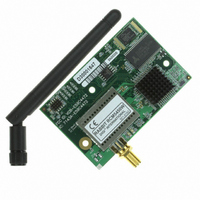
... RCM5400W module. The items in the Development Kit and their use are as follows. • RCM5400W module with 2.4 GHz dipole antenna. • Prototyping Board. • Universal AC adapter DC (includes Canada/Japan/U.S., Australia/N.Z., U.K., and European style plugs). Development Kits sold in North America may contain an AC adapter with only a North American style plug. ...
Page 11
... Online Documentation The online documentation is installed along with Dynamic C, and an icon for the docu- mentation menu is placed on the workstation’s desktop. Double-click this icon to reach the menu. If the icon is missing, use your browser to find and load folder, found in the Dynamic C installation folder. ...
Page 12
... Reorient or relocate the receiving antenna. • Increase the separation between the equipment and the receiver. • Connect the equipment into an outlet on a circuit different from that to which the receiver is connected. • Consult the dealer or an experienced radio/TV technician for help. ...
Page 13
... FCC identification number electronically. This exterior label can use wording such as the following: “Contains Transmitter Module FCC ID: VCB-E59C4472” or “Contains FCC ID: VCB-E59C4472.” Any similar wording that expresses the same meaning may be used. The following caption must be included with documentation for any device incorporating the RCM5400W RabbitCore module. Caution — ...
Page 14
... Europe The marking shall include as a minimum: • the name of the manufacturer or his trademark; • the type designation; • equipment classification, (see below). Receiver Class Highly reliable SRD communication media, e.g., serving human life 1 inherent systems (may result in a physical risk to a person). ...
Page 15
... The installation allows you to choose the COM port that will be used. The default selec- tion is COM1. You may select any available port for Dynamic C’s use. If you are not cer- tain which port is available, select COM1. This selection can be changed later within Dynamic C ...
Page 16
... Remember to use ESD protection regardless of whether you are working with the RCM5400W module on the Prototyping Board or in your own OEM application. 2.2.1 Step 1 — Prepare the Prototyping Board for Development Snap in four of the plastic standoffs supplied in the bag of accessory parts from the Devel- opment Kit in the holes at the corners as shown in Figure 2 ...
Page 17
... Step 2 — Attach the Antenna to the RCM5400W Module Attach the antenna to the antenna SMA connector on the RCM5400W as shown in Figure 3. Figure 3. Attach the Antenna to the RCM5400W Module CAUTION: Do not remove the RF shield by the antenna since any attempt to remove the shield will damage the RF circuits underneath it. ...
Page 18
... Turn the RCM5400W module so that the mounting holes line up with the corresponding holes on the Prototyping Board. Insert the metal standoffs as shown in Figure 4, secure them from the bottom using the 4-40 × 3/16 screws and washers, then insert the module’s header J1 on the bottom side into socket RCM1 on the Prototyping Board. ...
Page 19
... Your PC should recognize the new USB hardware, and the LEDs in the shrink-wrapped area of the USB programming cable will flash — if you get an error message, you will have to install USB drivers. Drivers for Windows XP are available in the Dynamic C Drivers\Rabbit USB Programming Cable\WinXP_2K to install the USB drivers ...
Page 20
... AC adapter as shown in Figure 5, then press down on the plug until it clicks into place. Connect the AC adapter to 3-pin header J1 on the Prototyping Board as shown in Figure 5 above. The connector may be attached either way as long not offset to one side— the center pin always connected to the positive terminal, and either edge pin is ground. ...
Page 21
... Channel—the channel the access point is on (1–11). • Signal—the signal strength of the access point. • MAC—the hardware (MAC) address of access point. • Access Point SSID—the SSID the access point is using. OEM User’s Manual menu. Select Start Options > ...
Page 22
... Dynamic C menu. Select a slower Max download baud rate. Click dialog on the “Communications” tab in the Dynamic C menu. Choose a lower debug baud rate. Click message once this step is completed successfully. , check that the COM port OK to save ...
Page 23
... The user's manual also provides complete hardware reference information and software function calls for the RCM5400W series of modules and the Prototyping Board. For advanced development topics, refer to the Dynamic C User’s Manual, also in the online documentation set. 2.4.1 Technical Support NOTE: If you purchased your RCM5400W or RCM5450W through a distributor or through a Rabbit partner, contact the distributor or partner first for technical support ...
Page 24
RabbitCore RCM5400W ...
Page 25
... Wi-Fi features. NOTE: The sample programs assume that you have at least an elementary grasp of the C language. If you do not, see the introductory pages of the Dynamic C User’s Manual for a suggested reading list. In order to run the sample programs discussed in this chapter and elsewhere in this manual, 1. Your module must be plugged in to the Prototyping Board as described in Chapter 2, “ ...
Page 26
... Dynamic C STDIO window. Press “2” or “3” on your keyboard to select LED DS2 or DS3 on the Prototyping Board. Then follow the prompt in the Dynamic C or OFF. A logic low will light up the LED you selected. —demonstrates the use of assembly language to flash LEDs DS2 and • ...
Page 27
... TAMPERDETECTION.C mode. When an attempt is detected, the battery-backed onchip-encryption RAM on the Rabbit 5000 is erased. This battery-backed onchip-encryption RAM can be useful to store data such as an AES encryption key from a remote location. This sample program shows how to load and read the battery-backed onchip-encryption RAM and how to enable a visual indicator ...
Page 28
... Web server and stores a log of • SERIAL_FLASHLOG.C hits on the home page of the serial flash “server.” This log can be viewed and cleared from a browser at http://10.10.6.100/. You will likely have to first “configure” your net- work interface card for a “10Base-T Half-Duplex,” “100Base-T Half-Duplex,” “ ...
Page 29
... Serial Port D for • FLOWCONTROL.C CTS/RTS flow control with serial data coming from Serial Port C (TxC) at 115,200 bps. The serial data received are displayed in the To set up the Prototyping Board, you will need to tie TxD and RxD ...
Page 30
... Since the J4 header locations on the two Prototyping Boards are connected with wires, there are no slip-on jumpers either Prototyping Board. —This program demonstrates transmitting and then receiving an • SWITCHCHAR.C ASCII string on Serial Ports C and D. It also displays the serial data received from both ports in the window ...
Page 31
... If you plan to use the real-time clock functionality in your application, you will need to set the real-time clock. Use the SETRTCKB.C folder, and follow the onscreen prompts. The SAMPLES\RTCLOCK program in the Dynamic C SAMPLES\RTCLOCK how to read and set the real-time clock. OEM User’s Manual sample program from the Dynamic C RTC_TEST.C folder provides additional examples of sample 25 ...
Page 32
RabbitCore RCM5400W ...
Page 33
... Chapter 4 describes the hardware components and principal hardware subsystems of the RCM5400W. Appendix A, “RCM5400W Specifica- tions,” provides complete physical and electrical specifications. Figure 6 shows the Rabbit-based subsystems designed into the RCM5400W. Figure 6. RCM5400W Subsystems The 73.73 MHz frequency shown for the RCM5400W is generated using a 36.864 MHz crystal with the Rabbit 5000 clock doubler enabled. OEM User’ ...
Page 34
RCM5400W Digital Inputs and Outputs Figure 7 shows the RCM5400W pinouts for header J1. standard 2 × 25 IDC header with a nominal 1.27 mm pitch. Headers Figure 7. RCM5400W Pinout RabbitCore RCM5400W ...
Page 35
... Figure 8 shows the use of the Rabbit 5000 microprocessor ports in the RCM5400W modules. Figure 8. Use of Rabbit 5000 Ports The ports on the Rabbit 5000 microprocessor used in the RCM5400W are configurable, and so the factory defaults can be reconfigured. Table 2 lists the Rabbit 5000 factory defaults and the alternate configurations. OEM User’s Manual 29 ...
Page 36
... PB6 Input/Output 23 PB7 Input/Output 30 Default Use Alternate Use Reset input Slave port data bus (SD0–SD7) External I/O data bus (ID0–ID7) SCLKB External I/O Address IA6 SCLKA External I/O Address IA7 /SWR External I/O Address IA0 /SRD External I/O Address ...
Page 37
... PC3 Input/Output 28 PC4 Input/Output 29 PC5 Input/Output 30 PC6 Input/Output 31 PC7 Input/Output 32 PE0 Input/Output OEM User’s Manual Default Use Alternate Use TXD I/O Strobe I0 Timer C0 TCLKF RXD/TXD I/O Strobe I1 Timer C1 RCLKF Input Capture TXC/TXF I/O Strobe I2 Timer C2 RXC/TXC/RXF I/O Strobe I3 Timer C3 SCLKD ...
Page 38
Table 2. RCM5400W Pinout Configurations (continued) Pin Pin Name 33 PE1 Input/Output 34 PE2 Input/Output 35 PE3 Input/Output 36 PE4 Input/Output 37 PE5/SMODE0 Input/Output 38 PE6/SMODE1 Input/Output 39 PE7/STATUS Input/Output 32 Default Use Alternate Use I/O Strobe I1 A21 Timer ...
Page 39
... Pin Name 40 PD0 Input/Output 41 PD1 Input/Output 42 PD2 Input/Output 43 PD3 Input/Output 44 PD4 Input/Output 45 PD5 Input/Output OEM User’s Manual Default Use Alternate Use I/O Strobe I0 Timer C0 D8 INT0 SCLKD/TCLKF QRD1B IA6 I/O Strobe I1 Timer C1 D9 INT1 RXD/RCLKF QRD1A Input Capture I/O Strobe I2 Timer C2 ...
Page 40
Table 2. RCM5400W Pinout Configurations (continued) Pin Pin Name 46 PD6 Input/Output 47 PD7 Input/Output 48 Not Connected 49 Not Connected 50 GND 34 Default Use Alternate Use I/O Strobe I6 D14 PWM2 TXA/TXE IA7 I/O Strobe I7 D15 PWM3 ...
Page 41
... Parallel Port A can also be used as an external I/O data bus to isolate external I/O from the main data bus. Parallel Port B pins PB2–PB7 can also be used as an auxiliary address bus. When using the external I/O bus for any reason, you must add the following line at the beginning of your program ...
Page 42
Serial Communication The RCM5400W module does not have any serial driver or receiver chips directly on the board. However, a serial interface may be incorporated on the board the RCM5400W is mounted on. For example, the Prototyping Board has ...
Page 43
... NOCHARASSYINBRK #define RS232_NOCHARASSYINBRK This macro is already defined so that it is the default behavior for the sample programs in the Dynamic C SAMPLES\RCM5400W\SERIAL OEM User’s Manual Serial Port E Serial Port F RCLKE and RCLKF must be selected the same parallel port as TXE and TXF respectively. library requires you to define the macro folder ...
Page 44
... Alternate Uses of the Programming Port All three Serial Port A signals are available as • a synchronous serial port • an asynchronous serial port, with the clock line usable as a general CMOS I/O pin The programming port may also be used as a serial port via the programming cable. ...
Page 45
... VCO, PLL, and power amplifier necessary to implement an 802.11b/g radio. The AL2236 can transmit and receive data 11Mbits/s in the 802.11b mode and Mbits/s in the 802.11g mode. It supports 802.11b/g channels 1–13 (2.401 GHz to 2.472 GHz). Channel 14 is not used. The data modulate the channel carrier in such a way produce a spread spectrum signal within the 22 MHz channel bandwidth of the selected channel ...
Page 46
... Many countries specify the channel range and power limits for Wi-Fi devices operated within their borders, and these limits are set automatically in the RCM5400W in firmware according to the country or region. For example, only channels 1–11 are authorized for use in the United States or Canada, and so channels 12 and 13 are disabled. See Section 6.2.4.1 for additional information and sample programs demonstrating how to configure an end device to meet the regulatory channel range and power limit requirements ...
Page 47
... ESD protection by attaching P2 to chassis ground. There are two LEDs close to the RP-SMA antenna connector atP2, a green LED at DS2 ( LINK ) to indicate association with the Wi-Fi access point, and a yellow LED at DS1 ( ) to indicate activity. ACT OEM User’s Manual Region Macro Number ...
Page 48
... Run Mode when no programming cable is attached. When the Rabbit 5000 is reset, the operating mode is determined by the status of the SMODE pins. When the programming cable’s the SMODE pins are pulled high, placing the Rabbit 5000 in the Program Mode. When the programming cable’ ...
Page 49
... A program “runs” in either mode, but can only be downloaded and debugged when the RCM5400W is in the Program Mode. Refer to the Rabbit 5000 Microprocessor User’s Manual gramming port. 4.4.2 Standalone Operation of the RCM5400W Once the RCM5400W has been programmed successfully, remove the programming cable from the programming connector and reset the RCM5400W ...
Page 50
... The spectrum spreader will now remain off whenever you OK are in the project file where you defined the macro. NOTE: Refer to the Rabbit 5000 Microprocessor User’s Manual for more information on the spectrum-spreading setting and the maximum clock speed. 44 Options > ...
Page 51
... Writing to arbitrary flash memory addresses at run time is strongly discouraged. Instead, define a “user block” area to store persistent data. The functions writeUserBlock() and readUserBlock() are provided for this. Refer to the for additional information. ...
Page 52
RabbitCore RCM5400W ...
Page 53
... Dynamic C development environment. Debugging occurs while the application runs on the target. Alternatively, users can compile a program to an image file for later loading. Dynamic C runs on PCs under Windows NT and later— see Rabbit’s Technical Note TN257, Running Dynamic C additional information if you are using a Dynamic C under Windows Vista ...
Page 54
... C, SPI, GPS, file system. LCD display and keypad drivers. • Powerful language extensions for cooperative or preemptive multitasking • Loader utility program to load binary images into Rabbit targets in the absence of Dynamic C. • Provision for customers to create their own source code libraries and augment on-line help by creating “ ...
Page 55
... Certain function calls involve reading and storing calibration constants from/to the simulated EEPROM in flash memory located at the top 2K of the reserved user block memory area (3800–39FF). This leaves the address range 0–37FF in the user block available for your application. These address ranges may change in the future in response to the volatility in the flash memory market, in particular sector size ...
Page 56
... This flag is also stored in the battery-backed SRAM. When a protected variable is updated, the “inactive” copy is modified, and is made “active” only when the update is 100% complete. This assures the integrity of the data in case a reset or a power failure occurs during the update process ...
Page 57
... Summary of Initialization 1. I/O port pins are configured for Prototyping Board operation. 2. Unused configurable I/O are set as tied outputs. 3. RS-232 is not enabled. 4. LEDs are off. 5. The slave port is disabled. RETURN VALUE None. OEM User’s Manual LIB\Rabbit4000\RCM5xxx\RCM54xxW.LIB folder illustrate the use of SAMPLES\RCM5400W brdInit 51 ...
Page 58
... PARAMETERS the input port data register to poll (e.g., PADR) dataport the input port bit (0–7) to poll portbit the value receive value the duration of the timeout in seconds (enter 0 for no timeout) ...
Page 59
... In addition to the Web-based technical support included at no extra charge, a one-year telephone-based technical support subscription is also available for purchase. Visit our Web site at www.rabbit.com OEM User’s Manual for the latest patches, workarounds, and bug fixes. for further information and complete documentation. 53 ...
Page 60
RabbitCore RCM5400W ...
Page 61
... PCI, PCMCIA, CompactFlash, USB and SD/MMC interfaces, and Wi-Fi devices such as Web-based cameras and print servers. 802.11b/g can operate in one of two modes—in a managed-access mode (BSS), called an infrastructure mode unmanaged mode (IBSS), called the ad-hoc mode. The 802.11 standard describes the details of how devices access each other in either of these modes ...
Page 62
Commands issued to the chip set in the interface allow a host program to override the default configurations and execute functions implemented on the interface cards, for example, scanning for hosts ...
Page 63
... The programming cable must connect the programming header on the module to your PC. 4. Power must be applied to the module through the Prototyping Board. Refer to Chapter 2, “Getting Started,” if you need further information on these steps. To run a sample program, open it with the Each sample program has comments that describe the purpose and function of the pro- gram. Follow the instructions at the beginning of the sample program. Complete information on Dynamic C is provided in the Dynamic C User’ ...
Page 64
... Wi-Fi Setup Figure 11 shows how your development setup might look once you’re ready to proceed. 58 Figure 11. Wi-Fi Host Setup RabbitCore RCM5400W ...
Page 65
... USB port to program the RCM5400W module. You will need either an access point for an existing Wi-Fi network that you are allowed to access and have note- book connected to that network (infrastructure mode), or you will need at least a PDA or PC with Wi-Fi to use the ad-hoc mode. User’s Manual 59 ...
Page 66
... FIG 5 or TCPCONFIG 1 #define TCPCONFIG 5 NOTE: TCPCONFIG 0 is not supported for Wi-Fi applications. There are some other “standard” configurations for mented in the LIB\Rabbit4000\TCPIP\TCP_CONFIG.LIB is available in the Dynamic C TCP/IP User’s Manual. 60 library. This macro "255.255.255.0" "10.10.6.1" "10.10.6.1" (no DHCP) and TCPCONFIG 1 at the beginning of your program. ...
Page 67
... PC/Laptop/PDA Configuration This section shows how to configure your PC or notebook to run the sample programs. Here we’re mainly interested in the PC or notebook that will be communicating wirelessly, which is not necessarily the PC that is being used to compile and run the sample program on the RCM5400W module. ...
Page 68
... Connection program is running, you will be able to select the network from a list of available networks. You will have set your wireless network name with the Wi-Fi channel macros for the ad- hoc mode as explained in Section 6.3, “Dynamic C Wi-Fi Configurations.” 62 tab, and check . Now click on ...
Page 69
... The sample programs in Section 6.2.4.1 show how to set up the country- or region-specific attributes, but do not show the basic setup of a wireless network. The sample programs in Section 6.2.4.2 show the setup and operation of a wireless network — the sample program is ideal to demonstrate that the RCM5400W has been hooked up correctly and that the Wi-Fi setup is correct so that an access point can be found ...
Page 70
... RCM5400W will be deployed for any other requirements. 64 —demonstrates how the multi-domain options from the #define WIFI_REGION_VERBOSE —demonstrates how the region or country can be set at #define IFC_ STDIO window will dis- STDIO ...
Page 71
... IP address, and the SSID in the macros, which are reproduced below. #define TCPCONFIG 1 #define IFC_WIFI_ENCRYPTION IFPARAM_WIFI_ENCR_WEP User’s Manual —demonstrates the runtime selection of a static IP configura- sample program provides further exam- (defined below). After associating, the sample KEY0 ). The sample program then associates with the second ...
Page 72
... KEY_1 "0123456789abcdef0123456789" #define IFC_WIFI_SSID AP_0 #define _PRIMARY_STATIC_IP MY_ADDRESS_0 Modify the access point names and keys to match your access points and network. —sends out a series of pings to a RabbitCore module on an ad-hoc • WIFIPINGYOU.C Wi-Fi network. This sample program uses some predefined macros. The first macro specifies the default TCP/IP configuration from the Dynamic C library ...
Page 73
... Before you run this sample program, configure the Dynamic C library and your TCPCONFIG 1. Use macro definitions in the “Defines” tab in the Dynamic C Options > Project Options menu to modify any parameter settings. If you are not using DHCP, set the IP parameters to values appropriate to your network. ...
Page 74
... BROWSELED.C Two “device LEDs” are created along with two buttons to toggle them. Users can use their Web browser to change the status of the lights. The DS2 and DS3 LEDs on the Prototyping Board will match those on the Web page. As long as you have not modified ...
Page 75
... WPA PSK (Wi-Fi • PINGLED_WPA_PSK.C Protected Access with Pre-Shared Key). WPA is a more secure replacement for WEP. The implementation in the sample program supports use of the TKIP (Temporal Key Integrity Protocol) cypher suite. The sample program uses macros to configure the access point for WPA PSK, specify the TKIP cypher suite, assign the access point SSID, and set the passphrase ...
Page 76
... Now set up a continuous ping on another host, and observe the pings time out succes- sively, then succeed, depending on the LED state. —This program demonstrates using the SMTP library to send an e-mail when • SMTP.C the S2 and S3 switches on the Prototyping Board are pressed. LEDs DS2 and DS3 on the Prototyping Board will light up when e-mail is being sent ...
Page 77
... The use of quotation marks in the examples described in this chapter is important since the absence of quotation marks will be flagged with warning messages when encrypted librar- ies are used. Wi-Fi Parameters • Access Point SSID— IFC_WIFI_SSID the macro to a string for the SSID of the access point in the infra- IFC_WIFI_SSID structure (BSS) mode, or the SSID of the ad-hoc network in the ad-hoc (IBSS) mode ...
Page 78
... The following encryption options are available. IFPARAM_WIFI_ENCR_NONE — no encryption is used. • IFPARAM_WIFI_ENCR_ANY — any type of encryption is used. • IFPARAM_WIFI_ENCR_WEP — use WEP encryption. You will need to define at least • one WEP key (see below). IFPARAM_WIFI_ENCR_TKIP — use TKIP or WPA encryption. You will need to • ...
Page 79
... IFC_WIFI_WPA_PSK_HEXSTR \ "57A12204B7B350C4A86A507A8AF23C0E81D0319F4C4C4AE83CE3299EFE1FCD27" is valid for the SSID "rabbitTest" Using a passphrase is rather slow. It takes a Rabbit 5000 more than 20 seconds to gen- erate the actual 256-bit key from the passphrase. If you use a passphrase and WIFI_VERBOSE_PASSPHRASE corresponding to that passphrase and SSID. • Authentication algorithm— ...
Page 80
... Type “TCPCONFIG” in the Function Search field, and hit <ctrl-H> . Scroll down to the section on “Wi-Fi Configuration.” The Dynamic C TCP/IP <Enter> User’s Manual.(Volume 1) provides additional information about these macros and Wi-Fi also possible to redefine any of the above parameters dynamically using the function call ...
Page 81
... Configuring TCP/IP at Run Time There is one basic function call used to configure Wi-Fi and other network settings — . See the Dynamic C TCP/IP User’s Manual, Volume 1 for more informa- ifconfig() tion about this function call. 6.3.3 Other Key Function Calls Remember to call ...
Page 82
... Use the Technical Support e-mail form at www.rabbit.com/support/. If the sample programs ran fine, you are now ready to go on. An Introduction to TCP/IP and the Dynamic C TCP/IP User’s Manual.provide background and reference information on TCP/IP, and are available on the CD and on our Web site ...
Page 83
... Appendix A provides the specifications for the RCM5400W. OEM User’s Manual A A. RCM5400W PPENDIX S PECIFICATIONS 77 ...
Page 84
A.1 Electrical and Mechanical Characteristics Figure A-1 shows the mechanical dimensions for the RCM5400W. Figure A-1. RCM5400W Dimensions NOTE: All measurements are in inches followed by millimeters enclosed in parentheses. All dimensions have a manufacturing tolerance of ±0.01" (0.25 mm). ...
Page 85
... It is recommended that you allow for an “exclusion zone” of 0.04" (1 mm) around the RCM5400W in all directions when the RCM5400W is incorporated into an assembly that includes other printed circuit boards. An “exclusion zone” of 0.08" (2 mm) is recom- mended below the RCM5400W when the RCM5400W is plugged into another assembly. ...
Page 86
... SDLC/HDLC • 1 asynchronous clocked serial port shared with program- ming port • 1 clocked serial port shared with serial flash Maximum asynchronous baud rate = CLK/8 Slave port allows the RCM5400W to be used as an intelligent peripheral device slaved to a master processor ...
Page 87
... Power (pins unloaded) Operating Temperature Humidity Connectors Board Size Typical Average Antenna Output Power Compliance OEM User’s Manual RCM5400W 3.3 V.DC ±5% 625 mA @ 3.3 V while transmitting/receiving 175 mA @ 3.3 V while not transmitting/receiving -30°C to +75° 95%, noncondensing One RP-SMA antenna connector One 2 × 25, 1.27 mm pitch IDC signal header One 2 × ...
Page 88
A.1.1 Antenna The RCM5400W Development Kit includes a 2.4 GHz (+2 dB) dipole antenna whose dimensions are shown in Figure A-3. Figure A-3. RCM5400W Development Kit Dipole Antenna NOTE: All measurements are in inches followed by millimeters enclosed in parentheses. ...
Page 89
... SMT header with a 1.27 mm pin spacing. J2, the programming port × 5 header with a 1.27 mm pin spacing Figure A-4 shows the layout of another board for the RCM5400W to be plugged into. These reference design values are relative to one of the mounting holes. Figure A-4. User Board Footprint for RCM5400W OEM User’s Manual 83 ...
Page 90
... A[19:0], /CS[2:0], /OE[1:0], WE[1:0] D[7:0] I /IOWR, /IORD, /IOBEN DRIVE PA[7:0], PB[7:0], PC[7:0], PD[7:0], PH[7:0] PE[7:0] All other pins 84 Parameter Maximum Rating VDD IO (max. 3 –40°C to +85°C, VDD A Min 3.0 V 1.65 V 2 Typ Max 3.3 V 3 ...
Page 91
... Table A-5 lists the external capacitive bus loading for the various RCM5400W output ports. Be sure to add the loads for the devices you are using in your custom system and verify that they do not exceed the values in Table A-5. Table A-5. External Capacitive Bus Loading -20°C to +85°C Output Port All I/O lines with clock doubler enabled OEM User’ ...
Page 92
... Figure A-5 shows a typical timing diagram for the Rabbit 5000 microprocessor external I/O read and write cycles. Figure A-5. External I/O Read and Write Cycles—No Extra Wait States NOTE: /IOCSx can be programmed to be active low (default) or active high. 86 RabbitCore RCM5400W ...
Page 93
... The measurements are taken at the 50% points under the following conditions. • -20°C to 85° VDD • Internal clock to nonloaded CLK pin delay ≤ 85°C/3.0 V The clock to address output delays are similar, and apply to the following delays. • the clock to address delay adr • ...
Page 94
... PE5 or SMODE0 Output on J1 JP2 pin 37 PE7 or STATUS Output JP3 on J1 pin 39 JP4 Reserved for future use. 88 Pins Connected 1–2 PE6 2–3 SMODE1 1–2 PE5 2–3 SMODE0 1–2 PE7 2–3 STATUS 1–2 PE0 2–3 A20 RabbitCore RCM5400W Factory Default × × × × ...
Page 95
... Wi-Fi power supply control. NOTE: The jumper connections are made using 0 Ω surface-mounted resistors. OEM User’s Manual Pins Connected 1–2 ≤ 1MB 2–3 > 1MB Control disabled—Wi-Fi power 1–2 supply is always on Control enabled so that the Wi-Fi 2–3 power supply is under ...
Page 96
RabbitCore RCM5400W ...
Page 97
... RCM5400W and to build prototypes of your own circuits. The Prototyping Board has power-supply connec- tions and also provides some basic I/O peripherals (RS-232, LEDs, and switches), as well as a prototyping area for more advanced hardware development. OEM User’s Manual B. P ROTOTYPING B OARD ...
Page 98
B.1 Introduction The Prototyping Board included in the Development Kit makes it easy to connect an RCM5400W module to a power supply and a PC workstation for development. It also pro- vides some basic I/O peripherals (RS-232, LEDs, and switches), ...
Page 99
... The header plug leading to bare leads provided for overseas customers can be connected to the 3-pin header in either orientation. Users providing their own power supply should ensure that it delivers 8– The voltage regulators will get warm while in use. Regulated Power Supply • ...
Page 100
... NOTE: No analog signals are available on the Prototyping Board with the RCM5400W RabbitCore module installed since no analog signals are available on the RCM5400W’s header J1. —Two 3-wire or one 5-wire RS-232 serial ports are available on the Prototyp- • RS-232 ing Board at header J4. A 10-pin 0.1" pitch header strip installed at J4 allows you to connect a ribbon cable that leads to a standard DE-9 serial connector ...
Page 101
... B.2 Mechanical Dimensions and Layout Figure B-2 shows the mechanical dimensions and layout for the Prototyping Board. Figure B-2. Prototyping Board Dimensions NOTE: All measurements are in inches followed by millimeters enclosed in parentheses. All dimensions have a manufacturing tolerance of ±0.01" (0.25 mm). OEM User’s Manual 95 ...
Page 102
... Prototyping Area Connectors B.3 Power Supply The RCM5400W requires a regulated 3.0 V – 3 power source to operate. Depend- ing on the amount of current required by the application, different regulators can be used to supply this voltage. The Prototyping Board has an onboard +5 V switching power regulator from which a +3 ...
Page 103
... The analog signals are brought out to labeled points at header location J3 on the Prototyping Board. Although header J3 is unstuffed × 7 header can be added. Note that analog signals are not available when the RCM5400W included in the Development Kit installed. OEM User’s Manual 97 ...
Page 104
... The holes in the prototyping area are spaced at 0.1" (2.5 mm). +3 and GND traces run along the top edge of the prototyping area for easy access. Small to medium circuits can be prototyped using point-to-point wiring with AWG wire between the proto- typing area, the +3 and GND traces, and the surrounding area where surface- mount components may be installed ...
Page 105
... Figure B-5. Prototyping Board Current-Measurement Option NOTE: Once you have cut the trace below header location JP1 or JP2, you must either be using the ammeter or have a jumper in place in order for power to be delivered to the Prototyping Board. OEM User’s Manual 99 ...
Page 106
... RS-232 transceiver installed at U3. This transceiver provides the voltage output, slew rate, and input voltage immunity required to meet the RS-232 serial communication protocol. Basically, the chip translates the Rabbit 5000’s signals to RS-232 signal levels. Note that the polarity is reversed in an RS-232 circuit so that a +3.3 V output becomes approxi- mately -10 V and output as +10 V ...
Page 107
... RS232.LIB of the flow control lines are specified using a set of five macros. SERX_RTS_PORT—Data register for the parallel port that the RTS line is on (e.g., PCDR). SERA_RTS_SHADOW—Shadow register for the RTS line's parallel port (e.g., PCDRShadow). SERA_RTS_BIT—The bit number for the RTS line. ...
Page 108
... Header Description JP1 +5 V Current Measurement JP2 +3.3 V Current Measurement JP3 PC0/TxD/LED DS2 JP4 102 Pins Connected 1–2 Via trace or jumper 1–2 Via trace or jumper JP3 TxD on header J4 1–2 JP4 PC0 to LED DS2 1–2 n.c. PC0 available on header J2 Factory Default ...
Page 109
... PC3 to Switch S3 1–2 JP10 RxC on header J4 1–2 n.c. PC3 available on header J2 1–2 1–2 Connected: PB2 to LED DS2 n.c. PB2 available on header J2 1–2 1–2 Connected: PB3 to LED DS3 n.c. PB3 available on header J2 1–2 1–2 Connected: PB4 to Switch S2 n ...
Page 110
... JP24 LN0_IN–LN3_IN JP25 Thermistor Location NOTE: Jumper connections JP3–JP10, JP12, JP14, JP16, JP18, JP23, and JP24 are made using 0 Ω surface-mounted resistors. Jumper connections JP11, JP13, JP15, JP17, and JP19–JP22 are made using 470 Ω surface-mounted resistors. 104 Pins Connected 1– ...
Page 111
... Rabbit 5000 real-time clock to retain data with the RCM5400W powered down. Figure C-1. External Battery Connections A battery with a nominal voltage and a minimum capacity of 165 mA·h is recom- mended. A lithium battery is strongly recommended because of its nearly constant nominal voltage over most of its life. OEM User’s Manual C. P PPENDIX at Header J1 S ...
Page 112
... It reduces the battery voltage to the SRAM and to the real-time clock, thereby limiting the current consumed by the real-time clock and lengthening the battery life. • It ensures that current can flow only out of the battery to prevent charging the battery. • A voltage, VRAM, is supplied to Y3, the integrated 32.768 kHz oscillator, which keeps working when the voltage begins to drop ...
Page 113
... The +3.3 V supplied to the RCM5400W via header J1 powers most of the onboard circuits. In addition, there linear regulator that provides the core voltage to the Rabbit 5000 microprocessor. Other linear regulators supply the additional voltage levels needed by the Wi-Fi circuits. Figure C-3. RCM5400W Onboard Power Supplies OEM User’s Manual 107 ...
Page 114
RabbitCore RCM4400W ...
Page 115
... JP17 (LN3 buffer/filter to RCM5400W) ............ 103 JP18 (PB5/Switch S2) . 103 JP19 (LN4 buffer/filter to RCM5400W) ............ 103 JP2 (+ 3.3 V current mea- surement) .................. 102 JP20 (LN5 buffer/filter to RCM5400W) ............ 104 JP21 (LN6 buffer/filter to RCM5400W) ............ 104 JP22 (LN7 buffer/filter to RCM5400W) ............ 104 JP23 (analog inputs LN4– LN6 configuration) .. 104 109 ...
Page 116
... Prototyping Board JP24 (analog inputs LN0– LN3 configuration) ...104 JP3–JP4 (PC0/TxD/LED DS2) ..........................102 JP5–JP6 (PC1/RxD/Switch S2) .............................103 JP7–JP8 (PC2/TxC/LED DS3) ..........................103 JP9–JP10 (PC3/RxC/ Switch S3) ................103 RCM5400W ......................88 JP1 (FPGA chip select, PE6, or SMODE1 output on J1) ...
Page 117
... U user block determining size ................ 49 function calls ..................... 49 readUserBlock() ............ 45 writeUserBlock() ........... 45 reserved area for calibration constants ....................... 49 W Wi-Fi additional resources .......... 76 bring interface down ......... 75 bring interface up .............. 75 circuit description ............. 39 function calls ifconfig() ................. 71, 75 ifconfig(IF_WIFI0,… ifdown(IF_WIFI0) ........ 75 ifup(IF_WIFI0) ............. 75 sock_init() ..................... 75 sock_init_or_exit(1) ...... 75 tcp_tick(NULL) ............ 75 sample programs ............... 63 111 ...
Page 118
RabbitCore RCM4400W ...
Page 119
... RCM5400W Schematic www.rabbit.com/documentation/schemat/090-0266.pdf 090-0230 Prototyping Board Schematic www.rabbit.com/documentation/schemat/090-0230.pdf 090-0252 USB Programming Cable Schematic www.rabbit.com/documentation/schemat/090-0252.pdf You may use the URL information provided above to access the latest schematics directly. OEM User’s Manual S CHEMATICS 113 ...
Page 120
...