EZ80L925048MOD Zilog, EZ80L925048MOD Datasheet
EZ80L925048MOD
Specifications of EZ80L925048MOD
EZ80L925048MOD


Related parts for EZ80L925048MOD


EZ80L925048MOD Summary of contents
Page 1
... Module Product Specification PS017005-0903 PRELIMINARY ZiLOG Worldwide Headquarters • 532 Race Street • San Jose, CA 95126 Telephone: 408.558.8500 • Fax: 408.558.8300 • www.ZiLOG.com ...
Page 2
... San Jose, CA 95126 T elephone: 408.558.8500 Fax: 408.558.8300 www .ZiLOG.com ZiLOG is a registered trademark of ZiLOG Inc. in the United States and in other countries. All other products and/or service names mentioned herein may be trademarks of the companies with which they are associated. Document Disclaimer © 2003 by ZiLOG, Inc. All rights reserved. Information in this publication concerning the devices, applications, or technology described is intended to suggest possible uses and may be superseded ...
Page 3
... Physical Dimensions . . . . . . . . . . . . . . . . . . . . . . . . . . . . . . . . . . . . . . . . . . . . . 17 Mounting the Module onto the eZ80 ESD/EMI Protection . . . . . . . . . . . . . . . . . . . . . . . . . . . . . . . . . . . . . . . . . . . . . 20 Absolute Maximum Ratings . . . . . . . . . . . . . . . . . . . . . . . . . . . . . . . . . . . . . 20 Power Supply . . . . . . . . . . . . . . . . . . . . . . . . . . . . . . . . . . . . . . . . . . . . . . . . . . 21 Document Number Description . . . . . . . . . . . . . . . . . . . . . . . . . . . . . . . . . . . . . 22 Change Log . . . . . . . . . . . . . . . . . . . . . . . . . . . . . . . . . . . . . . . . . . . . . . . . . 22 Schematic Diagrams . . . . . . . . . . . . . . . . . . . . . . . . . . . . . . . . . . . . . . . . . . . . . 23 Customer Feedback Form . . . . . . . . . . . . . . . . . . . . . . . . . . . . . . . . . . . . . . . . . 32 The eZ80L92 Module Product Specification . . . . . . . . . . . . . . . . . . . . . . . . 32 PS017005-0903 eZ80L92 Module Product Specification ® Development Platform . . . . . . . . . . . . . . eZ80L925048MOD iii Table of Content s ...
Page 4
... Customer Information . . . . . . . . . . . . . . . . . . . . . . . . . . . . . . . . . . . . . . . . . 32 Product Information . . . . . . . . . . . . . . . . . . . . . . . . . . . . . . . . . . . . . . . . . . . 32 Return Information . . . . . . . . . . . . . . . . . . . . . . . . . . . . . . . . . . . . . . . . . . . . 32 Problem Description or Suggestion . . . . . . . . . . . . . . . . . . . . . . . . . . . . . . . 32 PS017005-0903 eZ80L92 Module Product Specification eZ80L925048MOD iv Table of Contents ...
Page 5
... Figure 13. eZ80L92 Module Schematic Diagram 9—E-NET Module . . . 27 Figure 14. eZ80L92 Module Schematic Diagram 9—IrDA Reset . . . . . . 28 Figure 15. eZ80L92 Module Schematic Diagram 9—Headers . . . . . . . . 29 Figure 16. eZ80L92 Module Schematic Diagram 9—Power Supply . . . 30 Figure 17. eZ80L92 Module Schematic Diagram 9—Control Logic . . . . 31 PS017005-0903 eZ80L92 Module Product Specification eZ80L925048MOD iv List of Figures ...
Page 6
... List of Tables Table 1. eZ80L92 Module Peripheral Bus Connector Pin Identification Table 2. eZ80L92 Module I/O Connector Pin Identification . . . . . . . . . . . . . . . . . 8 Table 3. Ethernet Connector Pin Assignments . . . . . . . . . . . . . . . . . . . . . . . . . 13 Table 4. Chip Frequency to Wait State Cycle Time Calculation Table 5. Absolute Maximum Ratings . . . . . . . . . . . . . . . . . . . . . . . . . . . . . . . . . 20 PS017005-0903 eZ80L92 Module Product Specification eZ80L925048MOD v List of Tables ...
Page 7
... Internet/Intranet connectivity. This low-cost, expandable module is powered by ZiLOG’s latest power-efficient, high-speed, optimized pipeline architecture eZ80L92 device (eZ80L925048MOD), a member of ZILOG’s new eZ80 The eZ80L92 microprocessor is a high-speed single-cycle instruction-fetch micro- processor, which can operate with a clock speed of 48 MHz ...
Page 8
... WORD is active Low, and B/W, for which BYTE is active Low. Block Diagram Figure 1 illustrates a block diagram of the eZ80L92 Module. PS017005-0903 eZ80L92 Module Product Specification ® instructions for efficient block data transfer pin for battery backup eZ80L925048MOD 2 ® CPU core The eZ80L92 Module ...
Page 9
... Figure 1. eZ80L92 Module Functional Block Diagram PS017005-0903 eZ80L92 Module Product Specification Gold Cap 32 KHz XTAL XTAL/Osc. Real-Time Clock eZ80 CPU Watch-Dog UART Timer UART ZDI/JTAG SPI 2 I C/SPI 6 Timer Bus Controller 1 MB 128/512 KB Flash/ROM SRAM eZ80L925048MOD 3 Power-On Reset RJ45 10 BaseT Controller w/ Magnetics The eZ80L92 Module ...
Page 10
... Module Product Specification JP1 A10 V3.3_EXT A13 A15 A14 11 12 A18 GND_EXT A19 A12 A11 A20 A17 23 24 DIS_FLASH 25 26 A21 V3.3_EXT 27 28 A22 A23 29 30 CS0 CS1 31 32 CS2 GND_EXT MREQ IOREQ INSTRD 47 48 BUSREQ 49 50 HEADER 25X2 IDC50 eZ80L925048MOD 4 Pin Description ...
Page 11
... Signal Direction Comments Bidirectional Bidirectional Bidirectional Bidirectional V /Ground (0 V). SS 3.3 V Supply Input Pin. Bidirectional Bidirectional Bidirectional Bidirectional Bidirectional Bidirectional Bidirectional Bidirectional Bidirectional V /Ground (0 V). SS Bidirectional Bidirectional Bidirectional Bidirectional Bidirectional Bidirectional Bidirectional Bidirectional or GND, depending on their inactive levels to reduce power eZ80L925048MOD 5 Pin Description ...
Page 12
... Development Platform for external memory purposes; CMOS Input 3 tolerant). Bidirectional 3.3 V supply input pin. Bidirectional Bidirectional Output Output Output Bidirectional Bidirectional Bidirectional Bidirectional Bidirectional Bidirectional V /Ground (0 V). SS Bidirectional Bidirectional Bidirectional or GND, depending on their inactive levels to reduce power eZ80L925048MOD 6 ® ® Pin Description ...
Page 13
... To prevent EMI, the EZ80CLK output can be deactivated via software in the eZ80L92 Peripheral Power-Down Register. All inputs are CMOS level 3 tolerant), except where otherwise noted. PS017005-0903 eZ80L92 Module Product Specification Signal Direction Comments Bidirectional V /Ground (0 V). SS Bidirectional Bidirectional Output Output Input or GND, depending on their inactive levels to reduce power eZ80L925048MOD 7 Pin Description ...
Page 14
... TCK TMS 31 32 RTC_VDD EZ80CLK 33 34 IICSCL 35 36 IICSDA 37 38 FLASHWE 39 40 DIS_IRDA CS3 41 42 RESET WAIT 43 44 GND_EXT 45 46 NMI HEADER 25X2 IDC50 Signal Direction Comments Bidirectional Bidirectional or GND, depending on their inactive levels, to reduce power eZ80L925048MOD GND_EXT Pin Description 8 ...
Page 15
... Module Product Specification Signal Direction Comments Bidirectional Bidirectional Bidirectional Bidirectional Bidirectional Bidirectional V /Ground (0 V). SS Bidirectional Bidirectional Bidirectional Bidirectional Bidirectional Bidirectional Bidirectional Bidirectional Bidirectional Bidirectional V /Ground (0 V). SS Bidirectional Bidirectional Bidirectional Bidirectional Bidirectional Bidirectional or GND, depending on their inactive levels, to reduce power eZ80L925048MOD 9 Pin Description ...
Page 16
... Reset output from Module or push-button reset. Input Driving the WAIT pin Low forces the eZ80 provide additional clock cycles for an external peripheral or external memory to complete its Read or Write operation. 3.3 V supply input pin. or GND, depending on their inactive levels, to reduce power eZ80L925048MOD 10 ® CPU to Pin Description ...
Page 17
... NMI signal is combined with an internal NMI signal generated from the WDT block before being con- nected to the NMI input of the eZ80 3.3 V supply input pin. NC Reserved—No Connection. or GND, depending on their inactive levels, to reduce power eZ80L925048MOD 11 ® CPU ® CPU. Pin Description ...
Page 18
... Base-T Ethernet. This LAN LED should RX+ is connected to TX+ and RX– is connected to TX–. A steady Link LED (bot- tom) indicates Traffic (RX or TX) on the LAN. PS017005-0903 eZ80L92 Module Product Specification (PS0130). pin is available on the I/O connector of the module to connect eZ80L925048MOD eZ80L92 Prod- Onboard Component Description 12 ...
Page 19
... If LAN activity is detected, the LANACT signal is pulled Low. The LANACT is con- nected to GPIO input PD6 and can be used in interrupt edge-detection mode to wake up and reinitialize the Ethernet chip. A zero-Ohm resistor at position R15 on PS017005-0903 eZ80L92 Module Product Specification Pin Function 1 TX+ 2 TX– 3 RX+ 6 RX– Onboard Component Description eZ80L925048MOD 13 ...
Page 20
... Table 4. Chip Frequency to Wait State Cycle Time Calculation PS017005-0903 eZ80L92 Module Product Specification ) to (Intel bus mode with four system clock cycles per bus 84h ) to 0xB3 Write MHz Cycle Time eZ80L925048MOD (0 wait states for I/O). For a 18h access time is: Onboard Component Description 14 ...
Page 21
... PS017005-0903 eZ80L92 Module Product Specification (no wait states). 08h cycle that could possibly follow. For Write ) to , then set the Chip Select Control register 0xF0h 82h ) to . These settings select Intel Bus Mode with 0xAAh 08h eZ80L925048MOD Onboard Component Description 15 ...
Page 22
... Do not connect an RS-232 interface without level shifters. Note: UART1 can be used for modem attachment communications port to a host computer, where the embedded Ethernet module emulates an AT-style modem for internet access. UART1 does not offer onboard RS232-level shifters. PS017005-0903 eZ80L92 Module Product Specification Onboard Component Description eZ80L925048MOD 16 ...
Page 23
... The size of the eZ80L92 Module PCB 64mm. With an RJ45 Ethernet con- nector, the overall height is 25 mm, as shown in Figure 4. 13.7 mm 8.3 mm max. 1 2.54 mm PS017005-0903 eZ80L92 Module Product Specification 63.5 mm Link LAN 16.3 mm RJ45 3.5 mm Top View 9 mm IrDA 2.7 mm 6.2 mm 55.88 mm Figure 4. Dimension Drawing eZ80L925048MOD 16 mm 8.5 mm LEDs Onboard Component Description 17 ...
Page 24
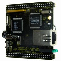
... Figure 5 illustrates a top view of the eZ80L92 Module. Figure 6 illustrates a bottom view of the eZ80L92 Module. PS017005-0903 eZ80L92 Module Product Specification Figure 5. Top Layer Figure 6. Bottom Layer eZ80L925048MOD Onboard Component Description 18 ...
Page 25
... Development Platform RJ45 63.5 mm (rear) E-NET Module H = 4.5 mm 1.7 mm Carrier Board RJ45 (rear) E-NET Module H = 4.5 mm Modem or Power Supply 50.5 mm max Carrier Board Figure 7. Mounting Examples eZ80L925048MOD ® Development Platform. See 1 15.3 mm I/O 8 I/O 8.5 mm Onboard Component Description 19 ...
Page 26
... For improved reliability, unused inputs should be tied to one of the supply voltages (V Parameter Standard operating temperature Storage temperature Operating Humidity (RH @ 50ºC) Operating Voltage (±5%) PS017005-0903 eZ80L92 Module Product Specification Table 5. Absolute Maximum Ratings Min 0 –45 25% — eZ80L925048MOD Max Units +70 ºC +85 ºC 90% 3.3 V Onboard Component Description 20 ...
Page 27
... Circuit Device GND V SS 3.3V U1 LM2575S-ADJ VIN VOUT O N 330uH/ 100n D1 1A/30V 3 5 LDO 5V 3.3V U1 LM3940 470uF/6.3V 100n Figure 8. Power Supply Examples eZ80L925048MOD To Module V DD 3.3V R1 5k6 1% C3 470uF/6.3V R2 Low ESR 3k3 1% GND V DD 3.3V Low ESR GND Onboard Component Description 21 ...
Page 28
... January 2003 05 September 2003 PS017005-0903 eZ80L92 Module Product Specification Product Specification Unique Document Number Revision Number Month and Year Published Purpose By Original issue M. Staubermann, R. Pujar Minor modifications M. Staubermann, R. Beebe Minor modifications R. Beebe Minor modifications R. Beebe Minor modifications R. Beebe eZ80L925048MOD 22 Document Number Description ...
Page 29
... IRDA_SD -DIS_FL -DIS_FL PD[0..7] -DIS_IRDA -DIS_IRDA PB[0..7] -CS[0..3] -CSFLASH PC[0..7] -CSFLASH PD[0..7] -RESFLASH -RESFLASH -CS[0..3] JTAG[1..4] TDO V3.3 GND eZ80L925048MOD 23 08 Connector Headers -RESET -FLASHWE -IOREQ -MREQ -INSTRD -WAIT -HALT_SLP -BUSREQ -BUSACK -NMI CLK_OUT RTC_VDD IICSDA IICSCL D[0..7] A[0..23] ...
Page 30
... BUSACK -BUSREQ 53 BUSREQ R29 -NMI 52 NMI -RESET 51 10k RESET R32 RTC_XOUT 220 Y3 C20 18pF 32.768kHz XTAL3 RTC_XIN C24 18pF eZ80L925048MOD 24 48 MHz HC49SM 1M R27 C17 4.7pF C25 220pF V3.3 R28 100 D1 TMM BAT 41 MINIMELF_AK GoldCap C19 0,1F GOLDCAP_SD V3.3 VDD VSS ...
Page 31
... VSS VDD I/O2 I/ I/O3 I/O4 -WR A11 A14 A12 A13 A9 A10 A12 A11 A10 A19 A17 N.C. 512kx8 SRAM SOJ36.400 C7 100nF U2D 9 8 74LVC04/SO U2F 13 12 74LVC04/SO PRELIMINARY eZ80L925048MOD eZ80L92 Module Product Specification RN1 4.7k V3.3 VDD VSS GND Schematic Diagrams 25 ...
Page 32
... DFLASH7 DQ7 -CSFLASH -RESFLASH VPP 11 VPP R2 A21 29 N.C. A20 38 A20/A21 used for N.C. 16/32Mbit-Flash MT28F008B3VG TSOP40.20MM C8 100nF A22/A23 not used here PRELIMINARY eZ80L925048MOD eZ80L92 Module Product Specification VDD R1 10K U2A -FLASHWE 2 1 74LVC04/SO V3.3 VDD VSS GND Schematic Diagrams 26 ...
Page 33
... TXD+ TD 8R2 R25 3 RXD- RD- CTD 4 CRD 5 6 R26 100 8 RXD+ RD+ C14 C15 100nF JP4 100nF HEADER 1 SIP1 don't stuff CASE eZ80L925048MOD 27 R20 R21 220 220 0603 0603 TD GND HFJ11-1041 HALOFASTJACK TX+ <-> 1 TX- <-> 2 RX+ <-> 3 RX- <-> 6 Schematic Diagrams ...
Page 34
... C10 MAX6328UR29 10nF SOT-23-L3 0603 IR-transceiver V3.3 R5 C11 68R 330nF R6 U5 2R7, 0.25W 5 1206 VCC (MMA 020 4) 1 LEDA IRDA_TXD 2 TXD IRDA_SD 4 SD IRDA_RXD 3 RXD 6 GND ZHX1810 PRELIMINARY eZ80L925048MOD eZ80L92 Module Product Specification -RESET V3.3 VDD VSS GND Schematic Diagrams 28 ...
Page 35
... D2 IICSCL IICSDA -FLASHWE GND_EXT -CS3 -IOREQ -RESET V3.3_EXT - -HALT_SLP -INSTRD V3.3_EXT -BUSREQ HEADER 25X2 IDC50 eZ80L925048MOD 29 PB6 PB4 PB2 PB0 PC7 PC5 PC3 PC1 PD7 GND_EXT PD4 PD2 PD0 TDI TRIGOUT TMS EZ80CLK GND_EXT -DIS_IRDA -WAIT GND_EXT -NMI Schematic Diagrams ...
Page 36
... Imax = 460mA (IrDA in use) Ityp = 100mA PCB1 E-NET Module Rev.B 98Cxxxx-xxx Figure 16. eZ80L92 Module Schematic Diagram 9—Power Supply PS017005-0903 eZ80L92 Module Product Specification common power plane V3 47uF 47uF 1nF TAJC TAJC GND common ground plane PRELIMINARY eZ80L925048MOD 100nF 1nF 100nF Schematic Diagrams ...
Page 37
... R14 0R PD7 -SLEEP R15 0R PD6 -ACTIVE don’t stuff R35 0 -WAIT PD0 IRDA_TXD = PD1 IRDA_RXD = IRDA_SD -CSFLASH -RESET -RESFLASH = -CSFLASH IRDA_SD V3.3 VDD VSS GND eZ80L925048MOD 31 SD[0..7] SA[0..3] -ETHRD -ETHWR ETHIRQ -SLEEP -ACTIVE IOCHRDY IRDA_TXD IRDA_RXD IRDA_SD -RESFLASH -CSFLASH Schematic Diagrams ...
Page 38
... Provide a complete description of the problem or your suggestion. If you are reporting a specific problem, include all steps leading up to the occurrence of the problem. Attach additional pages as necessary. _____________________________________________________________________________________________ _____________________________________________________________________________________________ _____________________________________________________________________________________________ _____________________________________________________________________________________________ _____________________________________________________________________________________________ PS017005-0903 eZ80L92 Module Product Specification Country Phone Fax Email eZ80L925048MOD 32 Customer Feedback Form ...