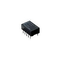
G6HU-2-DC12 Omron, G6HU-2-DC12 Datasheet

G6HU-2-DC12
Specifications of G6HU-2-DC12
Available stocks
Related parts for G6HU-2-DC12
G6HU-2-DC12 Summary of contents
Page 1
... This value was measured at a switching frequency of 120 operations/min and the criterion of contact resistance is 50 Ω. This value may vary depending on the operating environment. Always double-check relay suitability under actual operating conditions. DISCONTINUED Contact form G6H-2 G6H-2F Contact form Single coil latching G6HU-2 Resistive load (p. 0. 125 VAC VDC Ag (Au clad 125 VAC, 110 VDC 1 A 62.50 VA μ ...
Page 2
... Coil (VDC) (mA) resistance (Ω) 3 46.70 64.30 5 28.10 178 6 23.30 257 9 15.50 579 12 11.70 1,028 24 8.30 2,880 48 5.8 8,228 Single Coil Latching Type (G6HU-2) Rated voltage Rated current Coil (VDC) (mA) resistance (Ω) 3 33. 250 6 16.70 360 9 11.10 810 12 8.30 1,440 24 6.25 3,840 ...
Page 3
... UL Recognized (File No. E41515) / CSA Certified (File No. LR31928 Ambient Temp. = 40°C Type G6H-2(F) DPDT G6HU-2 G6HK-2 Note: 1. The rated values approved by each of the safety standards (e.g., UL, CSA, TUV) may be different from the performance characteristics individually defined in this catalog the interest of product improvement, specifications are subject to change. ...
Page 4
... Rated operating current (A) Single Coil Latching (G6HU- VDC Ambient temperature (°C) Condition: The Units were shocked at the rate of 500 m/s three times each in the ±X, ±Y, and ±Z directions with and without voltage imposed on the Units until the Units malfunctioned ...
Page 5
High-frequency Characteristics (See notes 1 and 2.) Frequency vs. Isolation (Average value) 0 Unit: G6H-2 Unit: G6H-2 Number of Units 100 100 200 500 1,000 Frequency (MHz) Distribution of Operate and Release Time (See note ...
Page 6
... Non-latching G6H-2 14.3 max. (14.1)* 0.25 5.4 max. (5.0)* 3.5+0.3 2.54 G6H-2F 14.3 max. (14.1)* 6.6 max. (6.3)* ■ Latching G6HU-2 14.3 max. (14.1)* 0.25 5.4 max. (5.0)* 3.5 2.54 G6HK-2 14.3 max. (14.1)* 0.25 5.4 max. (5.0)* 3.5 2.54 ...
Page 7
... VDC 0.5 A, 125 VAC Tape Packing (Surface Mounting Terminal Models) When ordering Relays in tape packing, add the prefix “-TR” to the model number otherwise the Relays in stick packing will be provided. Relays per Reel: 500 Direction of Relay Insertion Orientation mark Top tape (cover tape) ...
Page 8
... Claw Securing Force During Automatic Mounting During automatic insertion of Relays, be sure to set the securing force of each claw to the following so that the Relay’s characteristics will be maintained. C ...
Page 9
... Seller within 30 days of receipt of shipment. III. PRECAUTIONS 1. Suitability THE BUYER’S SOLE RESPOINSIBILITY TO ENSURE THAT ANY OMRON PRODUCT IS FIT AND SUFFICIENT FOR USE IN A MOTORIZED VEHICLE APPLICATION. BUYER SHALL BE SOLELY RESPONSIBLE FOR DETERMINING APPROPRIATENESS OF THE PARTICULAR PRODUCT WITH RESPECT TO THE BUYER’ ...
Page 10
... THE OMRON PRODUCT IS PROPERLY RATED AND INSTALLED FOR THE INTENDED USE WITHIN THE OVERALL EQUIPMENT OR SYSTEM. Complete “Terms and Conditions of Sale” for product purchase and use are on Omron’s website at http://www.components.omron.com – under the “About Us” tab, in the Legal Matters section. ...


