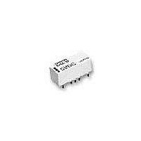
G6ZK-1F-A-DC5 Omron, G6ZK-1F-A-DC5 Datasheet

G6ZK-1F-A-DC5
Specifications of G6ZK-1F-A-DC5
Available stocks
Related parts for G6ZK-1F-A-DC5
G6ZK-1F-A-DC5 Summary of contents
Page 1
... G6Z-1FE G6Z-1PE-A G6Z-1FE-A G6Z-1P G6Z-1F G6Z-1P-A G6Z-1F-A G6ZU-1PE G6ZU-1FE G6ZU-1PE-A G6ZU-1FE-A G6ZU-1P G6ZU-1F G6ZU-1P-A G6ZU-1F-A G6ZK-1PE G6ZK-1FE G6ZK-1PE-A G6ZK-1FE-A G6ZK-1P G6ZK-1F G6ZK-1P-A G6ZK-1F-A 6. Contact arrangement None: Standard contact arrangement R: Reverse contact arrangement 7. Rated Coil Voltage 3, 4. 12, 24 G6Z 341 High-frequency Relay ...
Page 2
... Application Examples These Relays can be used for switching signals in media equipment. • Wire communications: Cable TV (STB and broadcasting infrastructure), cable modems, and VRS (video response systems) • Wireless communications: Transceivers, ham radios, ETC, ITS, high-level TV, satellite broadcasting, text multiplex broadcasting, mobile phone stations, TV broadcasting facilities, community antenna systems and car navigation systems • ...
Page 3
... Single Coil Latching Models G6ZU-1P(E), G6ZU-1F(E) Rated Rated voltage current (VDC) (mA) 3 66.7 4.5 44.4 5 40.0 9 22.2 12 16.7 24 8.3 Dual Coil Latching Models G6ZK-1P(E), G6ZK-1F(E) Rated Rated voltage current (VDC) (mA) 3 120 4 Note: 1. The rated current and coil resistance are measured at a coil temperature of 23°C with a tolerance of ±10%. ...
Page 4
... Must operate voltage Must release voltage 0 −60 −40 − 100 Ambient temperature (°C) Dual coil latching models models G6ZK-1P(E), G6ZK-1F(E) Shock Malfunction Y 1,000 Energized 800 600 Not X Z energized 1,000 1,000 400 200 200 400 1,000 1,000 Z' X' ...
Page 5
... Operating frequency (×10 operations) (Average value) + +20 +10 0 −10 −20 Sample: G6Z-1P 5 VDC Must operate voltage Number of Relays: 5 Must release voltage −30 −1,200 −800 −400 0 400 800 1,200 External magnetic field (A/m) (Average value) + +20 +10 0 −10 −20 Sample: G6Z-1P 5 VDC ...
Page 6
... Frequency (MHz) 30 Must operate bounce time Must release bounce time 25 Sample: G6Z-1P 75 Ω 5 VDC 20 Number of Relays 0.5 1.0 1.5 2.0 Time (ms) (Average value (initial value)) 0 1.7 Sample: G6Z-1PE 75 Ω 5 VDC with terminating resistance 1.6 Return loss 1 ...
Page 7
Dimensions Note: All units are in millimeters unless otherwise indicated. ■ PCB Through-hole Terminal Types G6Z-1PE G6Z-1PE-R G6ZU-1PE 20 8.6 8.9 3 6-0.6 0.2 (Coil 2.54 3-0.4 7.62 terminal) 7.62 15.24 Note: Each value has a tolerance of ±0.3 mm. ...
Page 8
... Note: Each value has a tolerance of ±0.3 mm. G6Z-1P-A G6ZU-1P-A 20 8.6 8.9 3 2.54 11-0.6 0.2 (Coil 7.62 7.62 terminal) 15.24 Note: Each value has a tolerance of ±0.3 mm. G6ZK-1PE 20 8.6 8.9 3 7-0.6 0.2 (Coil 2.54 3-0.4 7.62 terminal) 7.62 15.24 Note: Each value has a tolerance of ±0.3 mm. G6Z ...
Page 9
... G6ZK-1P 20 8.6 8.9 3 9-0.6 0.2 (Coil 2.54 7.62 3-0.4 terminal) 7.62 15.24 Note: Each value has a tolerance of ±0.3 mm. G6ZK-1P-A 20 8.6 8.9 3 2.54 12-0.6 0.2 (Coil 7.62 7.62 terminal) 15.24 Note: Each value has a tolerance of ±0.3 mm. Mounting Dimensions (Bottom View) Tolerance: ±0.1 mm Ten, 1 ...
Page 10
Surface Mount Terminal Types G6Z-1FE G6ZU-1FE 8.6 20 0.2 9.3 (Coil terminal) 6-0.6 9.6 2.54 3-0.4 7.62 15.24 Note 1: Each value has a tolerance of ±0.3 mm. 2: The coplanarity of the terminals is 0.1 mm max. G6Z-1FE-A ...
Page 11
... Note 1: Each value has a tolerance of ±0.3 mm. 2: The coplanarity of the terminals is 0.1 mm max. G6ZK-1FE-A 20 8.6 0.2 9.3 (Coil terminal) 2.54 Ten, 0.6 9.6 7.62 15.24 Note 1: Each value has a tolerance of ±0.3 mm. ...
Page 12
... Nine, 0.6 9.6 2.54 Three, 0.4 7.62 15.24 Note 1: Each value has a tolerance of ±0.3 mm. 2: The coplanarity of the terminals is 0.1 mm max. G6ZK-1F-A 20 8.6 0.2 9.3 (Coil terminal) 2.54 9.6 Twelve, 0.6 7.62 15.24 Note 1: Each value has a tolerance of ±0.3 mm. ...
Page 13
... Note: The radius of the unmarked corner is 0.3 mm. Do not quench the terminals after mounting. Clean the Relay using alcohol or water no hotter than 40°C max. The thickness of cream solder to be applied should be between 150 and 200 μm on OMRON’s recommended PCB pattern. Correct Soldering Relay Terminal ...
Page 14
... High-frequency Characteristics Measurement Method and Measurement Substrate High-frequency characteristics for the G6Z are measured in the way shown below. Consult your OMRON representative for details on 50-Ω models. Measurement Method for 75-W Models G6Z Network vector analyzer ...
Page 15
... Latching Relay Mounting Make sure that the vibration or shock that is generated from other devices, such as Relays, on the same panel or substrate and imposed on the Latching Relay does not exceed the rated value, oth- erwise the set/reset status of the Latching Relay may be changed. ...
Page 16
... All sales are subject to Omron Electronic Components LLC standard terms and conditions of sale, which can be found at http://www.components.omron.com/components/web/webfiles.nsf/sales_terms.html ALL DIMENSIONS SHOWN ARE IN MILLIMETERS. To convert millimeters into inches, multiply by 0.03937. To convert grams into ounces, multiply by 0.03527. OMRON ELECTRONIC COMPONENTS LLC 55 E. Commerce Drive, Suite B ...


