ISP1362BDFA ST-Ericsson Inc, ISP1362BDFA Datasheet - Page 148
ISP1362BDFA
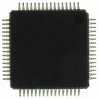
Manufacturer Part Number
ISP1362BDFA
Description
IC USB OTG CONTROLLER 64-LQFP
Manufacturer
ST-Ericsson Inc
Datasheet
1.ISP1362EEUM.pdf
(153 pages)
Specifications of ISP1362BDFA
Controller Type
USB 2.0 Controller
Interface
Parallel/Serial
Voltage - Supply
3 V ~ 3.6 V
Operating Temperature
-40°C ~ 85°C
Mounting Type
Surface Mount
Package / Case
64-LQFP
Lead Free Status / RoHS Status
Lead free / RoHS Compliant
Current - Supply
-
Other names
568-1219
ISP1362BD,151
ISP1362BD-S
ISP1362BD,151
ISP1362BD-S
Available stocks
Company
Part Number
Manufacturer
Quantity
Price
Company:

Part Number:
ISP1362BDFA
Manufacturer:
STE
Quantity:
5


NXP Semiconductors
27. Tables
Table 1.
Table 2.
Table 3.
Table 4.
Table 5.
Table 6.
Table 7.
Table 8.
Table 9.
Table 10. Special fields for ATL, interrupt and ISO . . . . .42
Table 11. Generic PTD structure: bit description . . . . . . .43
Table 12. ATL buffer area . . . . . . . . . . . . . . . . . . . . . . . .45
Table 13. Interrupt polling . . . . . . . . . . . . . . . . . . . . . . . .46
Table 14. Endpoint access and programmability . . . . . . .52
Table 15. Programmable buffer memory size . . . . . . . . .53
Table 16. Memory configuration example . . . . . . . . . . . .53
Table 17. Endpoint selection for the DMA transfer . . . . .55
Table 18. 8237 compatible mode: pin functions . . . . . . .55
Table 19. Summary of EOT conditions for a bulk
Table 20. Recommended EOT usage for isochronous
Table 21. OTG Control registers overview . . . . . . . . . . . .60
Table 22. OtgControl register: bit allocation . . . . . . . . . .60
Table 23. OtgControl register: bit description . . . . . . . . .61
Table 24. OtgStatus register: bit allocation . . . . . . . . . . .62
Table 25. OtgStatus register: bit description . . . . . . . . . .62
Table 26. OtgInterrupt register: bit allocation . . . . . . . . .63
Table 27. OtgInterrupt register: bit description . . . . . . . .64
Table 28. OtgInterruptEnable register: bit allocation . . . .65
Table 29. OtgInterruptEnable register: bit description . . .65
Table 30. OtgTimer register: bit allocation . . . . . . . . . . . .66
Table 31. OtgTimer register: bit description . . . . . . . . . .67
Table 32. OtgAltTimer register: bit allocation . . . . . . . . .67
Table 33. OtgAltTimer register: bit description . . . . . . . .68
Table 34. Host Controller registers overview . . . . . . . . . .68
Table 35. HcRevision register: bit allocation . . . . . . . . . .70
Table 36. HcRevision register: bit description . . . . . . . . .70
Table 37. HcControl register: bit allocation . . . . . . . . . . .70
Table 38. HcControl register: bit description . . . . . . . . . .71
Table 39. HcCommandStatus register: bit allocation . . .72
Table 40. HcCommandStatus register: bit description . .73
Table 41. HcInterruptStatus register: bit allocation . . . . .73
Table 42. HcInterruptStatus register: bit description . . . .74
Table 43. HcInterruptEnable register: bit allocation . . . . .74
Table 44. HcInterruptEnable register: bit description . . .75
Table 45. HcInterruptDisable register: bit allocation . . . .76
Table 46. HcInterruptDisable register: bit description . . .76
ISP1362_5
Product data sheet
Ordering information . . . . . . . . . . . . . . . . . . . . .4
Pin description . . . . . . . . . . . . . . . . . . . . . . . . . .7
Bus access priority table for the ISP1362 . . . .13
Buffer memory areas and their applications . .14
I/O port addressing . . . . . . . . . . . . . . . . . . . . .20
Registers used in addressing modes . . . . . . . .25
Recommended capacitor values . . . . . . . . . . .38
Port 1 function . . . . . . . . . . . . . . . . . . . . . . . . .40
Generic PTD structure: bit allocation . . . . . . . .42
endpoint . . . . . . . . . . . . . . . . . . . . . . . . . . . . . .57
endpoints . . . . . . . . . . . . . . . . . . . . . . . . . . . . .58
Rev. 05 — 8 May 2007
Table 47. HcFmInterval register: bit allocation . . . . . . . . 77
Table 48. HcFmInterval register: bit description . . . . . . . 77
Table 49. HcFmRemaining register: bit allocation . . . . . 78
Table 50. HcFmRemaining register: bit description . . . . 78
Table 51. HcFmNumber register: bit allocation . . . . . . . . 79
Table 52. HcFmNumber register: bit description . . . . . . 79
Table 53. HcLSThreshold register: bit allocation . . . . . . 79
Table 54. HcLSThreshold register: bit description . . . . . 80
Table 55. HcRhDescriptorA register: bit description . . . . 81
Table 56. HcRhDescriptorA register: bit description . . . . 81
Table 57. HcRhDescriptorB register: bit allocation . . . . . 82
Table 58. HcRhDescriptorB register: bit description . . . . 83
Table 59. HcRhStatus register: bit allocation . . . . . . . . . 83
Table 60. HcRhStatus register: bit description . . . . . . . . 84
Table 61. HcRhPortStatus[1:2] register: bit allocation . . 84
Table 62. HcRhPortStatus[1:2] register: bit description . 85
Table 63. HcHardwareConfiguration register:
Table 64. HcHardwareConfiguration register:
Table 65. HcDMAConfiguration register: bit allocation . . 90
Table 66. HcDMAConfiguration register: bit description . 90
Table 67. Buffer_Type_Select[2:0]: bit description . . . . . 91
Table 68. HcTransferCounter register: bit description . . . 91
Table 69. HcmPInterrupt register: bit allocation . . . . . . . 92
Table 70. HcmPInterrupt register: bit description . . . . . . 92
Table 71. HcmPInterruptEnable register: bit allocation . . 93
Table 72. HcmPInterruptEnable register: bit description 94
Table 73. HcChipID register: bit description . . . . . . . . . . 94
Table 74. HcScratch register: bit description . . . . . . . . . 95
Table 75. HcSoftwareReset register: bit description . . . . 95
Table 76. HcBufferStatus register: bit allocation . . . . . . . 95
Table 77. HcBufferStatus register: bit description . . . . . . 95
Table 78. HcDirectAddressLength register: bit allocation 96
Table 79. HcDirectAddressLength register:
Table 80. HcDirectAddressData register: bit description 97
Table 81. HcISTLBufferSize register: bit description . . . 97
Table 82. HcISTL0BufferPort register: bit description . . . 98
Table 83. HcISTL1BufferPort register: bit description . . . 98
Table 84. HcISTLToggleRate register: bit allocation . . . . 98
Table 85. HcISTLToggleRate register: bit description . . . 99
Table 86. HcINTLBufferSize register: bit description . . . 99
Table 87. HcINTLBufferPort register: bit description . . . . 99
Table 88. HcINTLBlkSize register: bit allocation . . . . . . 100
Table 89. HcINTLBlkSize register: bit description . . . . . 100
Table 90. HcINTLPTDDoneMap register:
bit allocation . . . . . . . . . . . . . . . . . . . . . . . . . . 88
bit description . . . . . . . . . . . . . . . . . . . . . . . . . 89
bit description . . . . . . . . . . . . . . . . . . . . . . . . . 97
bit description . . . . . . . . . . . . . . . . . . . . . . . . 100
Single-chip USB OTG Controller
© NXP B.V. 2007. All rights reserved.
ISP1362
continued >>
147 of 152
Related parts for ISP1362BDFA
Image
Part Number
Description
Manufacturer
Datasheet
Request
R

Part Number:
Description:
IC FILTR/CODEC 14BIT AUD 30TSSOP
Manufacturer:
ST-Ericsson Inc
Datasheet:
Part Number:
Description:
IC FILTR/CODEC 14BIT AUD 30TSSOP
Manufacturer:
ST-Ericsson Inc
Datasheet:

Part Number:
Description:
IC USB HUB CONTROLLER HS 80-LQFP
Manufacturer:
ST-Ericsson Inc
Datasheet:

Part Number:
Description:
IC USB HOST CONTROLLER 128-LQFP
Manufacturer:
ST-Ericsson Inc
Datasheet:

Part Number:
Description:
IC USB PERIPH CONTROLLER 64HVQFN
Manufacturer:
ST-Ericsson Inc
Datasheet:
Part Number:
Description:
IC USB HOST CTRL FULL-SPD 48HVQF
Manufacturer:
ST-Ericsson Inc
Datasheet:
Part Number:
Description:
IC USB CTRL HI-SPEED 64HVQFN
Manufacturer:
ST-Ericsson Inc
Datasheet:
Part Number:
Description:
IC USB CTRL HI-SPEED 64TFBGA
Manufacturer:
ST-Ericsson Inc
Datasheet:
Part Number:
Description:
IC USB CTRL HI-SPEED 64HVQFN
Manufacturer:
ST-Ericsson Inc
Datasheet:
Part Number:
Description:
IC USB CTRL SNGL CHIP 64TFBGA
Manufacturer:
ST-Ericsson Inc
Datasheet:
Part Number:
Description:
IC USB HOST/DEVICE CTRLR 64-LQFP
Manufacturer:
ST-Ericsson Inc
Datasheet:
Part Number:
Description:
IC USB CTRL HI-SPEED 128TFBGA
Manufacturer:
ST-Ericsson Inc
Datasheet:
Part Number:
Description:
IC USB CNTRLR FULL-SPD 48-TSSOP
Manufacturer:
ST-Ericsson Inc
Datasheet: