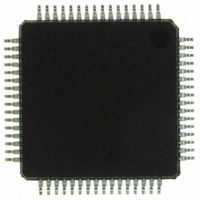
ISP1362BDFA ST-Ericsson Inc, ISP1362BDFA Datasheet - Page 45

ISP1362BDFA
Manufacturer Part Number
ISP1362BDFA
Description
IC USB OTG CONTROLLER 64-LQFP
Manufacturer
ST-Ericsson Inc
Datasheet
1.ISP1362EEUM.pdf
(153 pages)
Specifications of ISP1362BDFA
Controller Type
USB 2.0 Controller
Interface
Parallel/Serial
Voltage - Supply
3 V ~ 3.6 V
Operating Temperature
-40°C ~ 85°C
Mounting Type
Surface Mount
Package / Case
64-LQFP
Lead Free Status / RoHS Status
Lead free / RoHS Compliant
Current - Supply
-
Other names
568-1219
ISP1362BD,151
ISP1362BD-S
ISP1362BD,151
ISP1362BD-S
Available stocks
Company
Part Number
Manufacturer
Quantity
Price
Company:
Part Number:
ISP1362BDFA
Manufacturer:
STE
Quantity:
5
NXP Semiconductors
Table 11.
ISP1362_5
Product data sheet
Name
B3[3] Last (PTD)
Speed (low)
TotalBytes[9:0]
B5[6] Ping-Pong
B5[7] Paired
DirToken[1:0]
FunctionAddress[6:0]
B7[7:5] PollingRate
B7[4:0] StartingFrame
(interrupt only)
B7[7:0] StartingFrame
(ISO only)
Generic PTD structure: bit description
11.5 Features of the control and bulk transfer (aperiodic transfer)
•
•
•
•
•
Status update
by HC
No
No
No
No
No
No
No
No
No
A paired PTD is a special feature that provides high performance single endpoint bulk
transfer and handles set-up enumeration sequence within 1 ms. A paired PTD
consists of two PTDs serving the same endpoint of a device that are set active and
placed in the ATL RAM at the same time. A paired PTD is specially designed for high
performance of a single endpoint. They are identified by hardware by using the
‘Paired’ bit in the PTD.
Possible to send up to a maximum of 18 USB bulk packets in 1 ms frame
(1.152 MB/s) by using the paired PTD feature.
Provides the status of every transfer endpoints (PTD) by monitoring the
HcATLPTDDoneMap of the ISP1362. This register provides information on which
PTD transfers are complete.
Sets the IRQ after the user-specified number of transfers is done.
Skips any PTD that is wasting bandwidth by using HcATLPTDSkipMap.
Description
This indicates that it is the last PTD of a list. Logic 1 means that this PTD is
the last PTD. The last PTD is used only for ISO. This bit is not used in the
interrupt and ATL transfers. The last PTD is indicated by the HcINTLLastPTD
and HcATLLastPTD registers.
This bit indicates the speed of the endpoint.
0 — full-speed
1 — low-speed
This specifies the total number of bytes to be transferred with this data
structure. This can be greater than MaxPacketSize.
0 — This is the ping buffer of the paired buffer. Paired must be logic 1.
1 — This is the pong buffer of the paired buffer. Paired must be logic 1.
If this bit is set to logic 1, two PTDs of the same endpoint and address can be
made active at the same time. This bit is used with the Ping-Pong bit. The first
paired PTD always starts with Ping = 0. The Pong PTD payload can be sent
out only if the Ping PTD payload is sent out. You can also monitor
RAM_BUFFER _STATUS to see which PTD is currently active on the USB
line.
00 — set up
01 — OUT
10 — IN
11 — reserved
This field contains the USB address of the function containing the endpoint
that this PTD refers to.
These two fields together select a start frame number (5 bits) and polls the
interrupt device at a rate specified by PollingRate (3 bits); see
The Host Controller compares this byte with the current frame number (can be
accessed from the HcFmNumber register). The PTD will be processed and
sent out only if the starting frame number equals to the current frame number.
Rev. 05 — 8 May 2007
…continued
Single-chip USB OTG Controller
© NXP B.V. 2007. All rights reserved.
ISP1362
Section
11.6.
44 of 152


