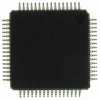
ISP1362BDFA ST-Ericsson Inc, ISP1362BDFA Datasheet - Page 62

ISP1362BDFA
Manufacturer Part Number
ISP1362BDFA
Description
IC USB OTG CONTROLLER 64-LQFP
Manufacturer
ST-Ericsson Inc
Datasheet
1.ISP1362EEUM.pdf
(153 pages)
Specifications of ISP1362BDFA
Controller Type
USB 2.0 Controller
Interface
Parallel/Serial
Voltage - Supply
3 V ~ 3.6 V
Operating Temperature
-40°C ~ 85°C
Mounting Type
Surface Mount
Package / Case
64-LQFP
Lead Free Status / RoHS Status
Lead free / RoHS Compliant
Current - Supply
-
Other names
568-1219
ISP1362BD,151
ISP1362BD-S
ISP1362BD,151
ISP1362BD-S
Available stocks
Company
Part Number
Manufacturer
Quantity
Price
Company:
Part Number:
ISP1362BDFA
Manufacturer:
STE
Quantity:
5
NXP Semiconductors
ISP1362_5
Product data sheet
Table 23.
Bit
15 to 12 -
11
10
9
8
7
6
5
4
3
Symbol
OTG_SE0_
EN
A_SRP_DET
_EN
A_SEL_SRP
SEL_HC_DC
LOC_
PULLDN_DM
LOC_
PULLDN_DP
A_RDIS_
LCON_EN
LOC_CONN
SEL_CP_
EXT
OtgControl register: bit description
Description
reserved
This bit is used by the Host Controller to send SE0 on remote connect.
0 — no SE0 sent on remote connect detection
1 — SE0 (bus reset) sent on remote connect detection
Remark: This bit is normally set when the B-device goes into the
b_wait_acon state (recommended sequence: LOC_CONN = 0
DELAY
cleared when it comes out of the b_wait_acon state.
This bit is for the A-device only. If set, the A_SRP_DET bit in the
OtgInterrupt register will be set on detecting an SRP event.
0 — disable
1 — enable
This bit is for the A-device to select a method to detect the SRP event
(V
0 — A-device responds to the V
1 — A-device responds to the data line pulsing
This bit is used to select either the Peripheral Controller or the Host
Controller that interfaces with the transceiver.
0 — Host Controller SIE is connected to the OTG transceiver
1 — Peripheral Controller SIE is connected to the OTG transceiver
0 — disconnects the on-chip pull-down resistor on DM of the OTG port
1 — connects the on-chip pull-down resistor on DM of the OTG port
0 — disconnects the on-chip pull-down resistor on DP of the OTG port
1 — connects the on-chip pull-down resistor on DP of the OTG port
This bit is for the A-device only. If set, the chip will automatically enable
its pull-up resistor on DP on detecting a remote disconnect event. If
cleared, the DP pull-up is controlled by the LOC_CONN bit.
0 — disable
1 — enable
Remark: This bit is normally set when the A-device goes into the
a_suspend state and is cleared when it comes out of the a_suspend
state. The LOC_CONN bit must be set before clearing this bit.
0 — disconnect the on-chip pull-up resistor on DP of the OTG port
1 — connect the on-chip pull-up resistor on DP of the OTG port
This bit is for the A-device only. This bit is used to choose the power
source to drive V
0 — use on-chip charge pump to drive V
1 — use external power source (5 V) to drive V
Remark: When using the external power source, the H_PSW1 pin
serves as the power switch that is controlled by the DRV_VBUS bit of
this register.
Rev. 05 — 8 May 2007
BUS
pulsing or data line pulsing).
50 s
BUS
OTG_SE0_EN = 1
.
BUS
Single-chip USB OTG Controller
pulsing
BUS
SEL_HC_DC = 0) and is
BUS
© NXP B.V. 2007. All rights reserved.
ISP1362
61 of 152


