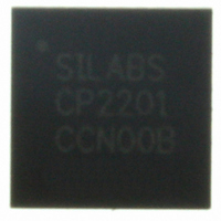
CP2201-GM Silicon Laboratories Inc, CP2201-GM Datasheet - Page 43

CP2201-GM
Manufacturer Part Number
CP2201-GM
Description
IC ETH CTRLR SNGL-CHIP 28QFN
Manufacturer
Silicon Laboratories Inc
Specifications of CP2201-GM
Package / Case
48-TQFP, 48-VQFP
Controller Type
Ethernet Controller, MAC/10Base-T
Interface
Parallel/Serial
Voltage - Supply
3.1 V ~ 3.6 V
Current - Supply
75mA
Operating Temperature
-40°C ~ 85°C
Mounting Type
Surface Mount
Ethernet Connection Type
1000BASE-T or 100BASE-T or 10BASE-T
Minimum Operating Temperature
- 40 C
Mounting Style
SMD/SMT
Product
Ethernet Controllers
Standard Supported
IEEE 802.3
Data Rate
10 Mbps or 100 Mbps or 1000 Mbps
Maximum Operating Temperature
+ 85 C
No. Of Ports
1
Ethernet Type
IEEE 802.3
Interface Type
Parallel
Supply Current
60mA
Supply Voltage Range
3.1V To 3.6V
Operating Temperature Range
-40°C To +85°C
Rohs Compliant
Yes
Lead Free Status / RoHS Status
Lead free / RoHS Compliant
For Use With
336-1326 - KIT REF DESIGN PWR OVER ETHERNET336-1316 - KIT EVAL FOR CP2201 ETH CTRLR
Lead Free Status / Rohs Status
Lead free / RoHS Compliant
Other names
336-1313
Available stocks
Company
Part Number
Manufacturer
Quantity
Price
Company:
Part Number:
CP2201-GM
Manufacturer:
SiliconL
Quantity:
48
Part Number:
CP2201-GMR
Manufacturer:
SILICON LABS/芯科
Quantity:
20 000
10. Power Modes
The CP2200/1 has four power modes that can be used to minimize overall system power consumption. The power
modes vary in device functionality and recovery methods. Each of the following power modes is explained in the
following sections:
The power modes above are achieved by disabling specific primary functions of the CP2200/1. Figure 15 shows
how power is distributed throughout the CP2200/1. To further reduce power consumption in any of the power
modes, secondary device functions may be turned off individually. The secondary device functions that may be
turned off are:
Normal Mode (Device Fully Functional)
Link Detection Mode (Transmitter Disabled)
Memory Mode (Transmitter and Receiver Disabled)
Shutdown Mode (Oscillator Output Disabled)
Link/Activity LED Drivers
Weak pull-ups to V
V
DD
(Oscillator)
System
Clock
VDD
Monitor
Parallel Host
Interface
MAC
OSCPWR.0
DD
Figure 15. Power and Clock Distribution Control
Flash Memory
TX and RX
Buffers
VDD Monitor
VDMCN.7
PHY
Rev. 1.0
PHYCN.7
(PHYCN.6)
(PHYCN.5)
TXEN
RXEN
IOPWR
Transmitter
Receiver
Activity LED
Link LED
Pullups
Weak
CP2200/1
All Digital Pins
LINK (LA) Pin
ACT Pin
43


