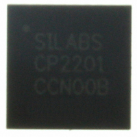
CP2201-GM Silicon Laboratories Inc, CP2201-GM Datasheet - Page 44

CP2201-GM
Manufacturer Part Number
CP2201-GM
Description
IC ETH CTRLR SNGL-CHIP 28QFN
Manufacturer
Silicon Laboratories Inc
Specifications of CP2201-GM
Package / Case
48-TQFP, 48-VQFP
Controller Type
Ethernet Controller, MAC/10Base-T
Interface
Parallel/Serial
Voltage - Supply
3.1 V ~ 3.6 V
Current - Supply
75mA
Operating Temperature
-40°C ~ 85°C
Mounting Type
Surface Mount
Ethernet Connection Type
1000BASE-T or 100BASE-T or 10BASE-T
Minimum Operating Temperature
- 40 C
Mounting Style
SMD/SMT
Product
Ethernet Controllers
Standard Supported
IEEE 802.3
Data Rate
10 Mbps or 100 Mbps or 1000 Mbps
Maximum Operating Temperature
+ 85 C
No. Of Ports
1
Ethernet Type
IEEE 802.3
Interface Type
Parallel
Supply Current
60mA
Supply Voltage Range
3.1V To 3.6V
Operating Temperature Range
-40°C To +85°C
Rohs Compliant
Yes
Lead Free Status / RoHS Status
Lead free / RoHS Compliant
For Use With
336-1326 - KIT REF DESIGN PWR OVER ETHERNET336-1316 - KIT EVAL FOR CP2201 ETH CTRLR
Lead Free Status / Rohs Status
Lead free / RoHS Compliant
Other names
336-1313
Available stocks
Company
Part Number
Manufacturer
Quantity
Price
Company:
Part Number:
CP2201-GM
Manufacturer:
SiliconL
Quantity:
48
Part Number:
CP2201-GMR
Manufacturer:
SILICON LABS/芯科
Quantity:
20 000
CP2200/1
10.1. Normal Mode
Normal Mode should is used whenever the host is sending or receiving packets. In this mode, the CP2200/01 is
fully functional. Typical Normal Mode power consumption is listed in Table 2 on page 9.
Note: When in normal mode, the transmitter has a power saving mode which is enabled on reset. This power saving mode dis-
10.2. Link Detection Mode
In Link Detection Mode, the transmitter and link pulse generation logic is disabled. The CP2200/1 will appear to be
“offline” because link pulses will not be generated. The most common way to use Link Detection Mode is enabling
the Wake-on-LAN interrupt, placing the CP2200/01 into Link Detection Mode, then placing the MCU in a low power
mode until the system is plugged into a network.
Note: When using link detection mode, the user should ensure that the link partner is always transmitting link pulses. An exam-
Note: A minimum transmitter return loss is specified in IEEE 802.3. If the transmitter is disabled, the TX± pins are placed in
From Normal Mode, the device can be placed in Link Detection Mode by clearing TXEN (PHYCN.6) to “0”. To
return the device to Normal Mode, disable the physical layer by clearing PHYCN to 0x00, then re-enable the
physical layer using the startup procedure in Section 15.7 on page 90.
10.3. Memory Mode
In Memory Mode, the physical layer (receiver and transmitter) is placed in a low-power state, and the CP2200/1
can neither send nor receive packets. The only primary functions of the device that remain functional are the Flash
memory and RAM buffers. The RAM buffers are only accessible using the Random Access method described in
Section 7.1 on page 23.
The device can be placed in Memory Mode by clearing the three most significant bits of the PHYCN register to
‘000’. The device can be returned to normal mode by setting the three most significant bits of the PHYCN register
to ‘111’ and waiting the appropriate physical layer turn-on times for both the transmitter and the receiver. The
physical layer electrical characteristics including turn-on time are specified in Table 22 on page 93. To return the
device to Normal Mode, disable the physical layer by clearing PHYCN to 0x00, then re-enable the physical layer
using the startup procedure in Section 15.7 on page 90.
10.4. Shutdown Mode
Shutdown Mode is the lowest power mode for the CP2200/1. All primary and secondary functions are disabled,
and the system clock is disconnected from the oscillator. The device can recover from Shutdown Mode only
through a power-on or pin reset.
The device can be placed in Shutdown Mode using the following procedure:
44
ables the transmitter's output driver and placed the TX+/- pins in high impedance when the CP220x is not transmitting
link pulses or data. To meet the minimum transmitter loss requirements in IEEE 802.3, this power saving mode should be
disabled. See Register 17, “TXPWR: Transmitter Power Register,” on page 46 for details.
ple of this type of device would be a hub or a switch. Some notebook PCs implement a power saving feature in which
they stop transmitting link pulses if a valid link is not detected. This would create a situation where both link partners are
waiting for each other to start transmitting link pulses.
high impedance mode and do not create the minimum return loss. The transmitter should not be disabled if the device is
considered "on a network" and valid link pulses are being received.
Step 1: Disable the PHY by clearing the three most significant bits of PHYCN to ‘000’.
Step 2: Disable the LED drivers by clearing bits 2 and 3 of IOPWR to ‘00’.
Step 3: Disable the V
Step 4: Disconnect the oscillator output from the rest of the device by clearing OSCOE (OSCPWR.0) to ‘0’.
This step should be performed last because the device will no longer respond until the next pin or
power-on reset.
DD
Monitor (optional) by clearing VDMEN (VDMCN.7) to ‘0’.
Rev. 1.0


