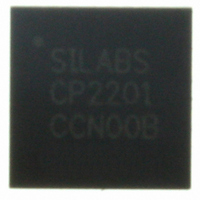
CP2201-GM Silicon Laboratories Inc, CP2201-GM Datasheet - Page 66

CP2201-GM
Manufacturer Part Number
CP2201-GM
Description
IC ETH CTRLR SNGL-CHIP 28QFN
Manufacturer
Silicon Laboratories Inc
Specifications of CP2201-GM
Package / Case
48-TQFP, 48-VQFP
Controller Type
Ethernet Controller, MAC/10Base-T
Interface
Parallel/Serial
Voltage - Supply
3.1 V ~ 3.6 V
Current - Supply
75mA
Operating Temperature
-40°C ~ 85°C
Mounting Type
Surface Mount
Ethernet Connection Type
1000BASE-T or 100BASE-T or 10BASE-T
Minimum Operating Temperature
- 40 C
Mounting Style
SMD/SMT
Product
Ethernet Controllers
Standard Supported
IEEE 802.3
Data Rate
10 Mbps or 100 Mbps or 1000 Mbps
Maximum Operating Temperature
+ 85 C
No. Of Ports
1
Ethernet Type
IEEE 802.3
Interface Type
Parallel
Supply Current
60mA
Supply Voltage Range
3.1V To 3.6V
Operating Temperature Range
-40°C To +85°C
Rohs Compliant
Yes
Lead Free Status / RoHS Status
Lead free / RoHS Compliant
For Use With
336-1326 - KIT REF DESIGN PWR OVER ETHERNET336-1316 - KIT EVAL FOR CP2201 ETH CTRLR
Lead Free Status / Rohs Status
Lead free / RoHS Compliant
Other names
336-1313
Available stocks
Company
Part Number
Manufacturer
Quantity
Price
Company:
Part Number:
CP2201-GM
Manufacturer:
SiliconL
Quantity:
48
Part Number:
CP2201-GMR
Manufacturer:
SILICON LABS/芯科
Quantity:
20 000
CP2200/1
12.6. Advanced Receive Buffer Operation
Receive buffer operation is automatically handled by hardware and does not require any assistance from the host
processor. Note: The information in this section is provided for reference purposes only and will typically
not be used except when debugging a problem and additional control over the receive buffer is required.
Figure 18 shows a detailed block diagram of the receive buffer. As packets arrive and pass through the receive
filter, they are added to the circular receive buffer at the address pointed to by the tail pointer. The FIFO tail pointer
is incremented after each byte is received. As soon as a new packet arrives, the receive buffer controller searches
for an unused TLB slot to store data about the received packet. If an unused TLB slot is found, it is claimed and
assigned to the packet currently being received by setting the slot’s valid bit to ‘1’. A Packet Received interrupt will
be generated after the entire packet is copied to the buffer. If all 8 slots are full (valid bits for all slots are set to ‘1’),
then the packet will be dropped and a Receive FIFO Full interrupt will be generated.
Each TLB slot holds information about its assigned packet such as starting address in the buffer, length, and
information about the packet such as the type (broadcast, multicast, unicast) and any errors that occurred during
reception (CRC error, incomplete packet, etc.). The receive buffer controller rotates through the TLB slots in a
circular fashion. For debugging purposes, the host processor may access any TLB slot using the TLB registers
listed in Table 17.
The oldest packet received starts at the address pointed to by the FIFO head pointer. This packet (packet #1 in
Figure 18) will be referred to as the current packet. The FIFO head pointer is used by the AutoRead interface to
read data from the current packet. As data is read using the AutoRead interface, the FIFO head pointer is
incremented until the entire packet is read out. Once the packet is read out, the host processor must clear the valid
bit of the packet by writing a ‘1’ to RXCLRV (RXCN.2). If the host processor chooses not to read the entire packet,
the valid bit should be cleared (and unread data skipped) by writing a ‘1’ to RXSKIP (RXCN.1).
A copy of the TLB slot associated with the current packet is always available by reading the CTLB registers listed in
Table 16. The same information can be obtained by reading CPTLB to determine the current TLB slot, then directly
accessing the slot using the registers in Table 17.
66
(e.g. 0 for TLB0)
RXAUTORD
Entry Number
Current TLB
Current TLB
Autoread interface automatically manages read pointers. TLB Entries are typically not
accessed by the host.
CPADDR
CPINFO/
CPLEN/
CPTLB
Copy of
(8-entry circular or random access)
Valid Bit
Translation Look-aside Buffer
0
1
1
1
0
0
0
0
Figure 18. Receive Buffer Block Diagram
Current packet address,
length, and information.
TLB0
TLB1
TLB2
TLB3
TLB4
TLB5
TLB6
TLB7
Rev. 1.0
FIFO Head Pointer
FIFO Tail Pointer
Packet #1
Packet #2
Packet #3
Receive
Buffer
4 KB


