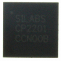
CP2201-GM Silicon Laboratories Inc, CP2201-GM Datasheet - Page 90

CP2201-GM
Manufacturer Part Number
CP2201-GM
Description
IC ETH CTRLR SNGL-CHIP 28QFN
Manufacturer
Silicon Laboratories Inc
Specifications of CP2201-GM
Package / Case
48-TQFP, 48-VQFP
Controller Type
Ethernet Controller, MAC/10Base-T
Interface
Parallel/Serial
Voltage - Supply
3.1 V ~ 3.6 V
Current - Supply
75mA
Operating Temperature
-40°C ~ 85°C
Mounting Type
Surface Mount
Ethernet Connection Type
1000BASE-T or 100BASE-T or 10BASE-T
Minimum Operating Temperature
- 40 C
Mounting Style
SMD/SMT
Product
Ethernet Controllers
Standard Supported
IEEE 802.3
Data Rate
10 Mbps or 100 Mbps or 1000 Mbps
Maximum Operating Temperature
+ 85 C
No. Of Ports
1
Ethernet Type
IEEE 802.3
Interface Type
Parallel
Supply Current
60mA
Supply Voltage Range
3.1V To 3.6V
Operating Temperature Range
-40°C To +85°C
Rohs Compliant
Yes
Lead Free Status / RoHS Status
Lead free / RoHS Compliant
For Use With
336-1326 - KIT REF DESIGN PWR OVER ETHERNET336-1316 - KIT EVAL FOR CP2201 ETH CTRLR
Lead Free Status / Rohs Status
Lead free / RoHS Compliant
Other names
336-1313
Available stocks
Company
Part Number
Manufacturer
Quantity
Price
Company:
Part Number:
CP2201-GM
Manufacturer:
SiliconL
Quantity:
48
Part Number:
CP2201-GMR
Manufacturer:
SILICON LABS/芯科
Quantity:
20 000
CP2200/1
15.7. Initializing the Physical Layer
The physical layer should be configured to the desired mode prior to setting the enable bit PHYEN (PHYCN.7). The
following procedure should be used to initialize the physical layer:
Note: Step 6 and Step 7 are repeated in the reset initialization procedure. Software only needs to perform these steps once.
90
Step 1: If auto-negotiation is used, implement the synchronization procedure in Section 15.2 on page 88.
Step 2: Disable the physical layer by writing 0x00 to the PHYCN register.
Step 3: Configure Desired Options using the PHYCN and PHYCF registers:
Step 4: Enable the physical layer:
Step 5: Wait for auto-negotiation to complete. If auto-negotiation is not enabled, software may wait for a valid
Step 6: Enable the desired Activity, Link, or Activity/Link LEDs using the Register 15, “IOPWR: Port Input/
Step 7: Initialize the MAC to the same duplex mode reported by the physical layer in the PHYCN register.
1.Specify the Duplex Mode or enable Auto-Negotiation.
2.Enable or Disable Loopback Mode.
3.Disable the transmitter power save mode (TXPWR = 0x80).
4.Enable the desired functions such as Receiver Smart Squelch, Automatic Polarity Correction, Link
5.If Automatic Polarity Correction is disabled, manually set the desired polarity.
1.Enable the physical layer (PHYEN = 1).
2.Wait for the physical layer to power up. See Physical Layer Startup Time in Table 22 on page 93.
3.Enable the transmitter and receiver (TXEN = 1 and RXEN = 1).
link or go directly to MAC Initialization.
Output Power Register,” on page 45.
Integrity, Jabber Protection, and PAUSE packet capability advertisement.
Rev. 1.0


