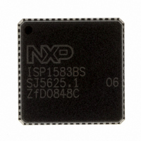
ISP1583BSUM ST-Ericsson Inc, ISP1583BSUM Datasheet - Page 17

ISP1583BSUM
Manufacturer Part Number
ISP1583BSUM
Description
IC USB PERIPH CONTROLLER 64HVQFN
Manufacturer
ST-Ericsson Inc
Datasheet
1.ISP1583BSUM.pdf
(100 pages)
Specifications of ISP1583BSUM
Controller Type
USB Peripheral Controller
Interface
Parallel/Serial
Voltage - Supply
3 V ~ 3.6 V
Current - Supply
47mA
Operating Temperature
-40°C ~ 85°C
Mounting Type
Surface Mount
Package / Case
64-VQFN Exposed Pad, 64-HVQFN, 64-SQFN, 64-DHVQFN
Lead Free Status / RoHS Status
Lead free / RoHS Compliant
Other names
568-1886-2
ISP1583BS,518
ISP1583BS-T
ISP1583BS,518
ISP1583BS-T
Available stocks
Company
Part Number
Manufacturer
Quantity
Price
Company:
Part Number:
ISP1583BSUM
Manufacturer:
MICRON
Quantity:
2 000
Company:
Part Number:
ISP1583BSUM
Manufacturer:
ST-ERICS
Quantity:
829
Part Number:
ISP1583BSUM
Manufacturer:
STE
Quantity:
20 000
NXP Semiconductors
ISP1583_7
Product data sheet
8.10 System controller
8.11 Modes of operation
8.8 SoftConnect
8.9 Reconfiguring endpoints
The USB connection is established by pulling pin DP (for full-speed devices) to HIGH
through a 1.5 k pull-up resistor. In the ISP1583, an external 1.5 k pull-up resistor must
be connected between pin RPU and 3.3 V. The RPU pin connects the pull-up resistor to
pin DP, when bit SOFTCT in the Mode register is set (see
hardware reset, the pull-up resistor is disconnected by default (bit SOFTCT = 0). The USB
bus reset does not change the value of bit SOFTCT.
When V
back-drive voltage.
The ISP1583 endpoints have a limitation when implementing a composite device with at
least two functionalities that require the support of alternate settings, for example, the
video class and audio class devices. The ISP1583 endpoints cannot be reconfigured on
the fly because it is implemented as a FIFO base. The internal RAM partition will be
corrupted if there is a need to reconfigure endpoints on the fly because of alternate
settings request, causing data corruption.
For details and work-around, refer to
application with alternate settings
The system controller implements the USB power-down capabilities of the ISP1583.
Registers are protected against data corruption during wake-up following a resume (from
the suspend state) by locking the write access, until an unlock code is written to the
Unlock Device register (see
The ISP1583 has two bus configuration modes, selected using pin BUS_CONF/DA0 at
power-up:
Details of bus configurations for each mode are given in
for each mode are given in
•
•
Split bus mode (BUS_CONF/DA0 = LOW): 8-bit multiplexed address and data bus,
and separate 8-bit or 16-bit DMA bus
Generic processor mode (BUS_CONF/DA0 = HIGH): separate 8-bit address and
16-bit data bus
BUS
is not present, the SOFTCT bit must be set to logic 0 to comply with the
Rev. 07 — 22 September 2008
Section
Table 90
(AN10071)”.
14.
Ref. 3 “Using ISP1582/3 in a composite device
and
Table
91).
Hi-Speed USB peripheral controller
Table
Table 24
5. Typical interface circuits
and
© NXP B.V. 2008. All rights reserved.
Table
ISP1583
25). After a
16 of 99


