DS21FT42 Maxim Integrated Products, DS21FT42 Datasheet - Page 39
DS21FT42
Manufacturer Part Number
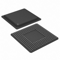
DS21FT42
Description
IC FRAMER T1 4X3 12CH 300-BGA
Manufacturer
Maxim Integrated Products
Datasheet
1.DS21FT42.pdf
(114 pages)
Specifications of DS21FT42
Controller Type
T1 Framer
Interface
Parallel/Serial
Voltage - Supply
2.97 V ~ 3.63 V
Current - Supply
225mA
Operating Temperature
0°C ~ 70°C
Mounting Type
Surface Mount
Package / Case
300-BGA
Lead Free Status / RoHS Status
Contains lead / RoHS non-compliant
Available stocks
Company
Part Number
Manufacturer
Quantity
Price


CCR5: COMMON CONTROL REGISTER 5 (Address=19 Hex)
(MSB)
TJC
SYMBOL
SYMBOL
TPCSI
TIRFS
TCM4
TCM3
TCM2
TCM1
TCM0
THSE
RFF
TJC
–
–
–
POSITION
POSITION
CCR4.3
CCR4.2
CCR4.1
CCR4.0
CCR5.7
CCR5.6
CCR5.5
CCR5.4
CCR5.3
CCR5.2
CCR5.1
CCR5.0
–
NAME AND DESCRIPTION
NAME AND DESCRIPTION
Receive Force Freeze. Freezes receive side signaling at
RSIG (and RSER if CCR4.7=1); will override Receive
Freeze Enable (RFE). See Section 14 for details.
0 = do not force a freeze event
1 = force a freeze event
Transmit Hardware Signaling Insertion Enable. See
Section 14 for details.
0 = do not insert signaling from the TSIG pin into the data
stream presented at the TSER pin.
1 = Insert the signaling from the TSIG pin into data stream
presented at the TSER pin.
Transmit Per–Channel Signaling Insert. See Section 14
for details.
0 = do not use TCHBLK to determine which channels should
have signaling inserted from the TSIG pin.
1 = use TCHBLK to determine which channels should have
signaling inserted from the TSIG pin.
Transmit Idle Registers (TIR) Function Select. See
Section 15 for timing details.
0 = TIRs define in which channels to insert idle code
1 = TIRs define in which channels to insert data from RSER
(i.e., Per = Channel Loopback function)
Transmit Japanese CRC6 Enable.
0 = use ANSI/AT&T/ITU CRC6 calculation (normal
operation)
1 = use Japanese standard JT–G704 CRC6 calculation
Not Assigned. Must be set to zero when written.
Not Assigned. Must be set to zero when written.
Transmit Channel Monitor Bit 4. MSB of a channel
decode that determines which transmit channel data will
appear in the TDS0M register. See Section 13 for details.
Transmit Channel Monitor Bit 3.
Transmit Channel Monitor Bit 2.
Transmit Channel Monitor Bit 1.
Transmit Channel Monitor Bit 0. LSB of the channel
decode.
TCM4
39 of 114
TCM3
TCM2
TCM1
TCM0
(LSB)
Related parts for DS21FT42
Image
Part Number
Description
Manufacturer
Datasheet
Request
R

Part Number:
Description:
MAX7528KCWPMaxim Integrated Products [CMOS Dual 8-Bit Buffered Multiplying DACs]
Manufacturer:
Maxim Integrated Products
Datasheet:
Part Number:
Description:
Single +5V, fully integrated, 1.25Gbps laser diode driver.
Manufacturer:
Maxim Integrated Products
Datasheet:
Part Number:
Description:
Single +5V, fully integrated, 155Mbps laser diode driver.
Manufacturer:
Maxim Integrated Products
Datasheet:
Part Number:
Description:
VRD11/VRD10, K8 Rev F 2/3/4-Phase PWM Controllers with Integrated Dual MOSFET Drivers
Manufacturer:
Maxim Integrated Products
Datasheet:
Part Number:
Description:
Highly Integrated Level 2 SMBus Battery Chargers
Manufacturer:
Maxim Integrated Products
Datasheet:
Part Number:
Description:
Current Monitor and Accumulator with Integrated Sense Resistor; ; Temperature Range: -40°C to +85°C
Manufacturer:
Maxim Integrated Products
Part Number:
Description:
TSSOP 14/A�/RS-485 Transceivers with Integrated 100O/120O Termination Resis
Manufacturer:
Maxim Integrated Products
Part Number:
Description:
TSSOP 14/A�/RS-485 Transceivers with Integrated 100O/120O Termination Resis
Manufacturer:
Maxim Integrated Products
Part Number:
Description:
QFN 16/A�/AC-DC and DC-DC Peak-Current-Mode Converters with Integrated Step
Manufacturer:
Maxim Integrated Products
Part Number:
Description:
TDFN/A/65V, 1A, 600KHZ, SYNCHRONOUS STEP-DOWN REGULATOR WITH INTEGRATED SWI
Manufacturer:
Maxim Integrated Products
Part Number:
Description:
Integrated Temperature Controller f
Manufacturer:
Maxim Integrated Products
Part Number:
Description:
SOT23-6/I�/45MHz to 650MHz, Integrated IF VCOs with Differential Output
Manufacturer:
Maxim Integrated Products
Part Number:
Description:
SOT23-6/I�/45MHz to 650MHz, Integrated IF VCOs with Differential Output
Manufacturer:
Maxim Integrated Products
Part Number:
Description:
EVALUATION KIT/2.4GHZ TO 2.5GHZ 802.11G/B RF TRANSCEIVER WITH INTEGRATED PA
Manufacturer:
Maxim Integrated Products
Part Number:
Description:
QFN/E/DUAL PCIE/SATA HIGH SPEED SWITCH WITH INTEGRATED BIAS RESISTOR
Manufacturer:
Maxim Integrated Products
Datasheet: