AD9952YSVZ Analog Devices Inc, AD9952YSVZ Datasheet - Page 25
AD9952YSVZ
Manufacturer Part Number
AD9952YSVZ
Description
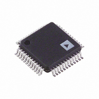
IC DDS 14BIT DAC 1.8V 48-TQFP
Manufacturer
Analog Devices Inc
Datasheet
1.AD9952YSVZ.pdf
(28 pages)
Specifications of AD9952YSVZ
Resolution (bits)
14 b
Master Fclk
400MHz
Tuning Word Width (bits)
32 b
Voltage - Supply
1.71 V ~ 1.96 V
Operating Temperature
-40°C ~ 105°C
Mounting Type
Surface Mount
Package / Case
48-TQFP Exposed Pad, 48-eTQFP, 48-HTQFP, 48-VQFP
Pll Type
Frequency Synthesis
Frequency
400MHz
Supply Voltage Range
1.71V To 1.89V
Digital Ic Case Style
TQFP
No. Of Pins
48
Operating Temperature Range
-40°C To +105°C
Msl
MSL 3 - 168 Hours
Lead Free Status / RoHS Status
Lead free / RoHS Compliant
For Use With
AD9952/PCB - BOARD EVAL FOR AD9952
Lead Free Status / RoHS Status
Lead free / RoHS Compliant, Lead free / RoHS Compliant
Available stocks
Company
Part Number
Manufacturer
Quantity
Price
Company:

Part Number:
AD9952YSVZ
Manufacturer:
TI
Quantity:
449
Company:
Part Number:
AD9952YSVZ
Manufacturer:
ADI
Quantity:
700
Company:
Part Number:
AD9952YSVZ
Manufacturer:
Analog Devices Inc
Quantity:
10 000
Part Number:
AD9952YSVZ
Manufacturer:
ADI/亚德诺
Quantity:
20 000
Company:
Part Number:
AD9952YSVZ-REEL7
Manufacturer:
Analog Devices Inc
Quantity:
10 000


AD9952
LAYOUT CONSIDERATIONS
For the best performance, the following layout guidelines
should be observed. Always provide the analog power supply
(AVDD) and the digital power supply (DVDD) on separate
supplies, even if just from two different voltage regulators
driven by a common supply. Likewise, the ground connections
(AGND, DGND) should be kept separate as far back to the
source as possible (for example, separate the ground planes on a
localized board, even if the grounds connect to a common point
in the system). Bypass capacitors should be placed as close to
the supply pin as possible. Usually, a multitiered bypassing
scheme consisting of a small high frequency capacitor (100 pF)
placed close to the supply pin and progressively larger capacitors
(0.1 µF, 10 µF) placed further away from the actual supply source
works best.
Rev. B | Page 25 of 28
Related parts for AD9952YSVZ
Image
Part Number
Description
Manufacturer
Datasheet
Request
R

Part Number:
Description:
BOARD EVAL FOR AD9952
Manufacturer:
Analog Devices Inc
Datasheet:


Part Number:
Description:
±1.7g Dual-Axis IMEMS Accelerometer Evaluation Board
Manufacturer:
Analog Devices Inc
Datasheet:
Part Number:
Description:
Inertial Sensor Evaluation System
Manufacturer:
Analog Devices Inc
Datasheet:
Part Number:
Description:
Manufacturer:
Analog Devices Inc
Datasheet:
Part Number:
Description:
Manufacturer:
Analog Devices Inc
Datasheet:
Part Number:
Description:
Manufacturer:
Analog Devices Inc
Datasheet:
Part Number:
Description:
Manufacturer:
Analog Devices Inc
Datasheet:
Part Number:
Description:
Manufacturer:
Analog Devices Inc
Datasheet:
Part Number:
Description:
Manufacturer:
Analog Devices Inc
Datasheet:
Part Number:
Description:
Manufacturer:
Analog Devices Inc
Datasheet:
Part Number:
Description:
Manufacturer:
Analog Devices Inc
Datasheet:
Part Number:
Description:
Manufacturer:
Analog Devices Inc
Datasheet: