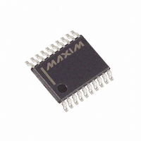
MAX3322EEUP+ Maxim Integrated Products, MAX3322EEUP+ Datasheet - Page 7

MAX3322EEUP+
Manufacturer Part Number
MAX3322EEUP+
Description
IC TXRX RS232 250KBPS 20TSSOP
Manufacturer
Maxim Integrated Products
Type
Transceiverr
Datasheet
1.MAX3323EEUE.pdf
(13 pages)
Specifications of MAX3322EEUP+
Number Of Drivers/receivers
2/2
Protocol
RS232
Voltage - Supply
3 V ~ 5.5 V
Mounting Type
Surface Mount
Package / Case
20-TSSOP
Lead Free Status / RoHS Status
Lead free / RoHS Compliant
Table 1. Tx/Rx Logic
Figure 4. Transmitter Outputs when Exiting Shutdown
High-input impedance is guaranteed from -13.0V to
+13.0V, when the receiver is in high-input-impedance
mode. The receiver is able to withstand the RS-232
maximum input voltage of ±25V.
Supply current falls to less than 10µA when the
MAX3322E/MAX3323E are placed in shutdown mode
(logic low). When in shutdown mode, the devices’
charge pumps are turned off, V+ decays to V
pulled to ground, the transmitter outputs and the
receiver outputs are disabled (high impedance), and
the receiver inputs are in high impedance (Table 1).
The device enters shutdown when V
The time required to exit shutdown is typically 50µs, as
shown in Figure 4. Connect SHDN to V
mode is not used.
TXENABLE
±15kV ESD-Protected, RS-232 Transceivers for
5V/div
2V/div
1
1
1
1
0
0
0
0
V
C1–C4 = 0.1µF
CC
= 3.3V
RENABLE
_______________________________________________________________________________________
1
1
0
0
1
1
0
0
50µs/div
SHDN
Shutdown Mode
0
1
0
1
0
1
0
1
L
or V
CC
CC
if shutdown
TRANSMITTER OUTPUT
is absent.
CC
T2
T1
, V- is
High-Z
High-Z
High-Z
High-Z
High-Z
High-Z
Active
Active
Unlike other RS-232 interface devices, in which the
receiver outputs swing between 0 and V
MAX3322E/MAX3323E feature a separate logic supply
input (V
sets thresholds for the transmit and shutdown inputs.
This feature allows a great deal of flexibility in interfac-
ing to many types of systems with different logic levels.
Connect this input to the host logic supply (1.65V ≤ V
≤ 5.5V).
To protect the MAX3322E/MAX3323E against ESD,
transmitters and receivers have extra protection against
static electricity to protect the device up to ±15kV. The
ESD structures withstand high ESD in all states: normal
operation, shutdown, and powered down. ESD protec-
tion can be tested in various ways; the transmitter and
receiver pins are characterized for protection to the fol-
lowing limits:
• ±15kV using the Human Body Model
• ±8kV using the IEC 1000-4-2 Contact Discharge
• ±15kV using the IEC 1000-4-2 Air-Gap method
Note: ESD performance depends on many conditions.
Contact Maxim for a reliability report that documents
test setup, test methodology, and test results.
Figure 5 shows the Human Body Model, and Figure 6
shows the current waveform it generates when dis-
charged into a low impedance. This model consists of
a 100pF capacitor charged to the ESD voltage of inter-
est, which is then discharged into the test device
through a 1.5kΩ resistor.
Multidrop Applications
method
L
) that sets V
RECEIVER OUTPUT
Enabled
Enabled
Enabled
Enabled
High-Z
High-Z
High-Z
High-Z
OUT
for the receiver outputs and
±15kV ESD Protection
V
L
Logic Supply Input
Human Body Model
RECEIVER INPUT
High-Z
High-Z
High-Z
High-Z
High-Z
High-Z
5kΩ
5kΩ
CC
, the
7
L


