AD53040KRP Analog Devices Inc, AD53040KRP Datasheet

IC PIN DRIVER W/INHIBIT 20-PSOP

AD53040KRP

Manufacturer Part Number
AD53040KRP
Description
IC PIN DRIVER W/INHIBIT 20-PSOP
Manufacturer
Analog Devices Inc
Type
Driverr
Datasheet

Specifications of AD53040KRP

Rohs Status
RoHS non-compliant
Number Of Drivers/receivers
1/0
Voltage - Supply
12V
Mounting Type
Surface Mount
Package / Case
20-PowerSOP Exposed Top Pad
Supply Voltage Max
19V
No. Of Outputs
1
Output Voltage
8V
Output Current
30mA
Driver Case Style
SOP
Msl
MSL 1 - Unlimited
Peak Reflow Compatible (260 C)
No
Device Type
Pin
Termination Type
SMD
No. Of Pins
20
Rohs Compliant
No
Protocol
-
Lead Free Status / RoHS Status
Contains lead / RoHS non-compliant

Available stocks

Company
Part Number
Manufacturer
Quantity
Price
Part Number:
AD53040KRPZ
Manufacturer:
ADI/亚德诺
Quantity:
20 000
a
PRODUCT DESCRIPTION
The AD53040 is a complete high speed pin driver designed for
use in digital or mixed-signal test systems. Combining a high
speed monolithic process with a unique surface mount package,
this product attains superb electrical performance while preserv-
ing optimum packaging densities and long-term reliability in an
ultrasmall 20-lead, SOP package with built-in heat sink.
Featuring unity gain programmable output levels of –3 V to
+8 V, with output swing capability of less than 100 mV to 9 V,
the AD53040 is designed to stimulate ECL, TTL and CMOS
logic families. The 500 MHz data rate capacity and matched
output impedance allows for real-time stimulation of these
digital logic families. To test I/O devices, the pin driver can
be switched into a high impedance state (Inhibit Mode), electri-
cally removing the driver from the path. The pin driver leakage
current inhibit is typically 100 nA and output charge transfer
entering inhibit is typically less than 20 pC.
REV. B
Information furnished by Analog Devices is believed to be accurate and
reliable. However, no responsibility is assumed by Analog Devices for its
use, nor for any infringements of patents or other rights of third parties
which may result from its use. No license is granted by implication or
otherwise under any patent or patent rights of Analog Devices.
FEATURES
500 MHz Driver Operation
Driver Inhibit Function
100 ps Edge Matching
Guaranteed Industry Specifications
High Speed Differential Inputs for Maximum Flexibility
Ultrasmall 20-Lead SOP Package with Built-In Heat Sink
APPLICATIONS
Automatic Test Equipment
Instrumentation and Characterization Equipment
50
Variable Output Voltages for ECL, TTL and CMOS
Semiconductor Test Systems
Board Test Systems
>1.5 V/ns Slew Rate
Output Impedance
The AD53040 transition from HI/LO or to inhibit is controlled
through the data and inhibit inputs. The input circuitry uses
high speed differential inputs with a common-mode range of
ECL timing or the simplicity of stimulating the pin driver from a
single ended TTL or CMOS logic source. The analog logic HI/LO
inputs are equally easy to interface. Typically requiring 10 A of
bias current, the AD53040 can be directly coupled to the
output of a digital-to-analog converter.
The AD53040 is available in a 20-lead, SOP package with a
built-in heat sink and is specified to operate over the ambient
commercial temperature range of –25 C to +85 C.
One Technology Way, P.O. Box 9106, Norwood, MA 02062-9106, U.S.A.
Tel: 781/329-4700
Fax: 781/326-8703
3 V. This allows for direct interface to precision differential
DATA
DATA
INH
INH
V
V
H
L
Ultrahigh Speed Pin Driver
FUNCTIONAL BLOCK DIAGRAM
AD53040
GND
V
CC
DRIVER
World Wide Web Site: http://www.analog.com
GND
V
CC
GND
with Inhibit Mode
V
EE
GND
1.0 A/K
50
V
GND
EE
© Analog Devices, Inc., 1999
AD53040
V
V
V
TV
THERM
HDCPL
LDCPL
OUT
CC
39nF
39nF

Related parts for AD53040KRP

AD53040KRP Summary of contents

Page 1

FEATURES 500 MHz Driver Operation Driver Inhibit Function 100 ps Edge Matching Guaranteed Industry Specifications 50 Output Impedance >1.5 V/ns Slew Rate Variable Output Voltages for ECL, TTL and CMOS High Speed Differential Inputs for Maximum Flexibility Ultrasmall 20-Lead ...

Page 2

AD53040–SPECIFICATIONS 3% unless otherwise noted. All temperature coefficients are measured and V and between V and HDCPL EE LDCPL Parameter DIFFERENTIAL INPUT CHARACTERISTICS Input Swing (Data to DATA, INH to INH) Max (DATA, DATA) ...

Page 3

... To ensure lead coplanarity ( 0.002 inches) and solderability, handling with bare hands should be avoided and the device should be stored in environments ( Model AD53040KRP 20-Lead Power SOIC Tube, 38 Pieces +260 C –3– AD53040 Units Test Conditions ns 4.0 ns Input, 10%/90% Output, ...

Page 4

AD53040 PIN FUNCTION DESCRIPTIONS Pin Pin Name Number Pin Functional Description Positive Power Supply. Both pins CC should be connected to minimize in- ductance and allow maximum speed of operation GND with a low inductance ...

Page 5

APPLICATION INFORMATION Power Supply Distribution, Bypassing and Sequencing The AD53040 draws substantial transient currents from its power supplies when switching between states and careful design of the power distribution and bypassing is key to obtaining speci- fied performance. Supplies should ...

Page 6

AD53040 DATA SMB U1 J1 MC10EL16 J4 1 SMB –5. C12 C21 50 50 0.01 F 0.1 F –2V C14 0.1 F INH SMB U2 J2 MC10EL16 1 ...

Page 7

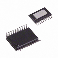
Thermally Enhanced Small Outline Package (PSOP) 0.2992 (7.60) 0.2914 (7.40) PIN 1 0.0118 (0.30) 0.0040 (0.10) STANDOFF REV. B OUTLINE DIMENSIONS Dimensions shown in inches and (mm). (RP-20) 0.5118 (13.00) 0.4961 (12.60 0.1890 (4.80) 0.4193 (10.65) HEAT ...

Related keywords