1711342-1 TE Connectivity, 1711342-1 Datasheet
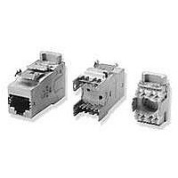
Telecom & Ethernet Connectors ASSY AMP-TWIST-6S SL JACK W/O DUST COVER

1711342-1

Manufacturer Part Number
1711342-1
Description
Telecom & Ethernet Connectors ASSY AMP-TWIST-6S SL JACK W/O DUST COVER
Manufacturer
TE Connectivity
Series
AMP-TWISTr
Datasheets

Specifications of 1711342-1

Product Type
Connector - Modular
Jack Type
RJ45
Wiring Pattern
Universal
Termination Style
SL Termination Tool
Keyed
No
Performance Category
Cat 6
Shielded
Yes
Number Of Positions
8
Netconnect Select System
Yes
Conductor O.d. (mm [in])
1.60 [0.0629]
Cable Diameter (max.) (mm [in])
9.00 [0.354]
Mount Type
Panel Mount
Wire Range (solid) (mm [awg])
22-24
Wire Range (stranded) (mm² [awg])
24-26
Contact Base Material
Beryllium Copper
Contact Plating, Mating Area, Material
Gold
Contact Plating, Mating Area, Thickness (µm [?in])
1.27 [50]
Housing Color
Gray
Housing Material
Zamak 5
Dust Cover
Without
Rohs/elv Compliance
RoHS compliant, ELV compliant
Lead Free Solder Processes
Not relevant for lead free process
Rohs/elv Compliance History
Converted to comply with RoHS directive
Packaging Method
Tray
Packaging Quantity
12
Lead Free Status / Rohs Status
No
1.
1.1 Content
TWIST* 6S Series SL Jack for Cat 6 component, Class E systems and Class E
to provide a universal connection interface between premise wiring of an office and the user’s network of
communications equipment (for data and voice networking systems).
other similar type fittings. Jacks incorporate IDC terminal for terminating both shielded and unshielded twisted
pair communications cable. Jacks will accommodate:
1.2 Qualification
inspections shall be performed using applicable inspection plan and product drawing.
2.
specified, the latest edition of the document applies. In the event of conflict between the requirements of this
specification and the product drawing, the product drawing shall take precedence. In the event of conflict
between the requirements of this specification and the referenced documents, this specification shall take
precedence.
2.1 TE Connectivity Documents.
Other applicable documents:
©2011 Tyco Electronics AMP España, S.A.U.
Barcelona (Spain)
All International Rights Reserved
Solid conductor cable
This specification covers performance, tests and quality requirements for AMP NETCONNECT*, AMP-
These assemblies are designed for installation into various outlet plates, surface mount boxes, panels and
When tests are performed on subject product line, procedures specified in Figure 1 shall be used. All
The following documents form a part of this specification to the extent specified herein. Unless otherwise
109-197:
230-702:
range (AWG)
SCOPE
APPLICABLE DOCUMENTS
22-24
Qualification Test report
Related Part Number
Customer drawing
Instruction sheet
Product Spec.
Document
AMP Test Specification vs. EIA and IEC Test Methods.
Supplier requirements for elimination of hazardous substances.
Stranded conductor cable
* Trademark
| Indicates change
Product
Specification
AMP-TWIST* 6S Series SL Jack
range (AWG)
24-26
C-1711160 / C-1711342
C-1711295 / C-1711343
1711160-1 / 1711342-1
1711295-1 / 1711342-1
* AMP, AMP NETCONNECT, AMP-TWIST, TE Connectivity logo are trade marks of
TE Connectivity
AMP-TWIST
411-93007 &
6S SL Jack
411-93014
insulation diameter
Max. conductor
108-93003
501-93016
1.60 mm
1711998-1 / 1711999-1
6S BASIC SL Jack
AMP-TWIST
C-1711998
C-1711999
411-93023
A
systems (min. length), used
Cable diameter range
5.0- 9.0 mm
108-93003
16/Mar/2011 Rev E
LOC IK
1 of 11

Related parts for 1711342-1

1711342-1 Summary of contents

Page 1

... AMP-TWIST 6S SL Jack 108-93003 411-93007 & 411-93014 C-1711160 / C-1711342 C-1711295 / C-1711343 1711160-1 / 1711342-1 1711295-1 / 1711342-1 501-93016 * AMP, AMP NETCONNECT, AMP-TWIST, TE Connectivity logo are trade marks of TE Connectivity 108-93003 16/Mar/2011 Rev E systems (min. length), used A Cable diameter range 1. ...

Page 2

Industrial Standards Standard A. ISO/IEC 11801. Second Edition 2002 – ANSI/TIA/EIA-568-B.2-1. Jun. 2002: C. DIN IEC 60512 D. DIN IEC 60068 E. ISO / IEC 60603-7-1 First Edition. 2002-01 F. ISO / IEC 60603-7-5 Ed.1.0 (09/2003) G. ...

Page 3

Tooling Connector has to be terminated with tooling PN 1725052-3 (tool kit). 3.6 Performance and Test Description Product is designed to meet electrical, mechanical and environmental performance requirements specified in Figure 1. Unless otherwise specified, all tests shall be ...

Page 4

Return loss Conn Hdw conf. FEXT (Far-end Crosstalk) Conn Hdw conf. PS FEXT (Power sum far end crosstalk) Conn Hdw conf. Delay Skew Conn Hdw conf. Transfer Impedance Conn Hdw conf. Return Loss Insertion Loss NEXT Loss PS NEXT Loss ...

Page 5

Vibration, Jack-plug interface and IDC-wire interface Durability, Jack-plug interface Plug insertion force, Jack-plug interface Plug withdrawal force, Jack-plug interface Plug retention in jack, Jack-plug interface Termination tensile strength, vertical, IDC-wire interface Durability repeated, IDC-wire interface Panel housing retention Front/rear housing ...

Page 6

Thermal shock. Jack-plug interface and IDC-wire interface Humidity-temperature cycling. Jack-plug interface and IDC-wire interface Humidity, steady state. Jack-plug interface and IDC-wire interface Stress relaxation, (dry heat). Jack-plug interface and IDC-wire interface Flowing mixed gas corrosion. Jack-plug interface and IDC-wire interface ...

Page 7

Product Qualification and Re-qualification Test Sequence. Examination of product ELECTRICAL Input-output Resistance Shield Contact resistance Input-output Resistance unbalance Current carrying capacity Insulation resistance Voltage proof MECHANICAL Vibration, Jack-plug interface and IDC-wire interface Durability, Jack-plug interface Plug insertion force, Jack-plug ...

Page 8

TRANSMISSION (Class E Permanent Link Configuration) – (See note c) A Examination of product Wire map and Shield continuity Return Loss Insertion Loss NEXT PS NEXT Loss ACR-N PS ACR-N FEXT ACR-F PS ACR-F Propagation Delay Delay Skew NOTE (a) ...

Page 9

Minimum number of samples required per each test group to be terminated with adequate cable. Test AWG 22 /Solid group ...

Page 10

Figures related to tests: Cable Metal braid Input/Output and shield resistance measurement points as shown * Resistance due to wire lengths and cable shielding shall be subtracted from all readings. NOTE Termination resistance of this assembly consists of plug to ...

Page 11

Termination Tensile Strength Vertical Pull Rev E Wire configuration Pull out each wire (x8) Figure 7 Figure 8 Front/Rear Housing retention 108-93003 INGF-070 ...

Related keywords