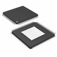
DS26303LN-75+ Maxim Integrated Products, DS26303LN-75+ Datasheet - Page 14

DS26303LN-75+
Manufacturer Part Number
DS26303LN-75+
Description
IC LIU E1/T1/J1 3.3V 144-ELQFP
Manufacturer
Maxim Integrated Products
Type
Line Interface Units (LIUs)r
Datasheet
1.DS26303L-120.pdf
(101 pages)
Specifications of DS26303LN-75+
Number Of Drivers/receivers
8/8
Protocol
T1/E1/J1
Voltage - Supply
3.135 V ~ 3.465 V
Mounting Type
Surface Mount
Package / Case
144-LQFP Exposed Pad, 144-eLQFP, 144-HLQFP
Lead Free Status / RoHS Status
Lead free / RoHS Compliant
MODESEL
TIMPRM
MOTEL/
NAME
CODE
CLKA
MUX/
CSB/
N.C.
JAS
PIN
93
94
11
43
88
87
HARDWARE AND PORT OPERATION
V
V
tri-state
(pulled
(pulled
(In HW
to V
mode,
pulled
TYPE
DDIO
DDIO
O,
to
to
I
I
I
I
I
SS
/2)
/2)
)
DS26303: 3.3V, T1/E1/J1, Short-Haul, Octal Line Interface Unit
Clock A. This output becomes a programmable clock output when
enabled (MC.CLKAE is set). For frequency options, see the
register. This option is not available in hardware mode. If this
option is not used, the pin should be left unconnected.
No Connection. Pin should be left unconnected or grounded.
Mode Selection. This pin is used to select the control mode of the
DS26303.
Low → Hardware Mode
V
High → Parallel Host Mode
Note: When left unconnected, do not route signals with fast
transitions near MODESEL. This practice minimizes capacitive
coupling.
Multiplexed/Nonmultiplexed Select Pin/
Transmit Impedance/Receive Impedance Match
MUX: In host mode with a parallel port, this pin is used to select
multiplexed address and data operation or separate address and
data. When mux is a high, multiplexed address and data is used.
TIMPRM: In hardware mode, this pin selects the internal transmit
termination impedance and receive impedance match for E1 mode
and T1/J1 mode.
0 → 75Ω for E1 mode or 100Ω for T1 mode
1 → 120Ω for E1 mode or 110Ω for J1 mode
Note: If the part number ends with 120, the default is 120
low and 75
Motorola Intel Select/Code
MOTEL: When in parallel host mode, this pin selects Motorola
mode when low and Intel mode when high.
CODE: In hardware mode, AMI encoding/decoding for all the LIUs
is selected when the pin is high. When the pin is low, B8ZS is
selected for T1 mode and HDB3 for E1 mode for all the LIUs.
Chip Select Bar/Jitter Attenuator Select
CSB: This signal must be low during all accesses to the registers.
JAS: In hardware mode, this pin is used as a jitter attenuator
select.
Low → Jitter attenuator is in the transmit path.
V
High → Jitter attenuator is in the receive path.
Note: When left unconnected in hardware mode, do not route
signals with fast transitions near JAS, in order to minimize
capacitive coupling.
14 of 101
DDIO
DDIO
/2 → Serial Host Mode
/2 → Jitter attenuator is not used.
Ω
when high for El mode only.
FUNCTION
Ω
when
CCR


