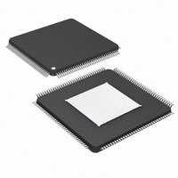
DS26303LN-75+ Maxim Integrated Products, DS26303LN-75+ Datasheet - Page 16

DS26303LN-75+
Manufacturer Part Number
DS26303LN-75+
Description
IC LIU E1/T1/J1 3.3V 144-ELQFP
Manufacturer
Maxim Integrated Products
Type
Line Interface Units (LIUs)r
Datasheet
1.DS26303L-120.pdf
(101 pages)
Specifications of DS26303LN-75+
Number Of Drivers/receivers
8/8
Protocol
T1/E1/J1
Voltage - Supply
3.135 V ~ 3.465 V
Mounting Type
Surface Mount
Package / Case
144-LQFP Exposed Pad, 144-eLQFP, 144-HLQFP
Lead Free Status / RoHS Status
Lead free / RoHS Compliant
SDO/RDY/ACKB/
D7/AD7/LP8
D6/AD6/LP7
D5/AD5/LP6
D4/AD4/LP5
D3/AD3/LP4
D2/AD2/LP3
D1/AD1/LP2
D0/AD0/LP1
RIMPOFF
NAME
INTB
PIN
83
82
28
27
26
25
24
23
22
21
V
I/O (In
mode,
pulled
TYPE
open
drain
DDIO
HW
I/O
O,
to
/2)
DS26303: 3.3V, T1/E1/J1, Short-Haul, Octal Line Interface Unit
Serial Data Out/Ready Output/Acknowledge Bar/Receive
Impedance Off
SDO: In serial host mode, the SDO data is output on this pin. If a
serial write is in progress this pin is in high impedance. During a
read SDO is high impedance when SDI is in command/
address mode. If CLKE is low, SDO is output on the rising edge of
SCLK, if CLKE is high, SDO is output on the falling edge. Data is
output LSB first.
RDY: A low on this pin reports to the host that the cycle is not
complete and wait states must be inserted. A high means the
cycle is complete.
ACKB: In Motorola parallel mode, a low on this pin indicates that
the read data is available for the host or that the written data cycle
is complete.
RIMPOFF: In hardware mode when this input pin is high, all the
RTIP and RING pins have internal impedance switched off.
Active-Low Interrupt Bar. This interrupt signal is driven low when
an event is detected on any of the enabled interrupt sources in any
of the register banks. When there are no active and enabled
interrupt sources, the pin can be programmed to either drive high
or not drive high (see Section 4.1.4). The reset default is to not
drive high when there are no active enabled interrupt sources. All
interrupt sources are disabled after a software reset and they must
be programmed to be enabled.
Data Bus 7–0/Address/Data Bus 7–0/Loopback Select 8–1
D[7:0]: In nonmultiplexed host mode, these pins are the
bidirectional data bus.
AD[7:0]: In multiplexed host mode, these pins are the bidirectional
address/data bus. Note that AD7 and AD6 do not carry address
information, and in serial host mode AD6–AD0 should be
grounded.
In serial host mode, this pin should be tied low.
LP[8:1] In hardware mode, these pins set the loopback modes for
the corresponding LIU as follows:
Low → Remote Loopback
V
High → Analog Loopback
Note: When left unconnected in hardware mode, do not route
signals with fast transitions near LP1–LP8. This practice minimizes
capacitive coupling.
16 of 101
DDIO
/2 → No Loopback
FUNCTION


