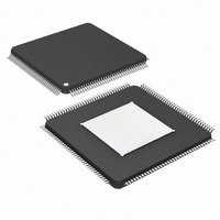
DS26303LN-75+ Maxim Integrated Products, DS26303LN-75+ Datasheet - Page 55

DS26303LN-75+
Manufacturer Part Number
DS26303LN-75+
Description
IC LIU E1/T1/J1 3.3V 144-ELQFP
Manufacturer
Maxim Integrated Products
Type
Line Interface Units (LIUs)r
Datasheet
1.DS26303L-120.pdf
(101 pages)
Specifications of DS26303LN-75+
Number Of Drivers/receivers
8/8
Protocol
T1/E1/J1
Voltage - Supply
3.135 V ~ 3.465 V
Mounting Type
Surface Mount
Package / Case
144-LQFP Exposed Pad, 144-eLQFP, 144-HLQFP
Lead Free Status / RoHS Status
Lead free / RoHS Compliant
6.3 Transmitter
NRZ data arrives on TPOSn and TNEGn on the transmit system side. The TPOSn and TNEGn data is sampled on
the falling edge of TCLKn
The data is encoded with HDB3 or B8ZS or AMI encoding when single-rail mode is selected (only TDATn as the
data source). When in single-rail mode only, BPV errors can be inserted for test purposes by register BEIR.
Encoded data is expected when dual-rail mode is selected. The encoded data passes through a jitter attenuator if it
is enabled for the transmit path. A digital sequencer and DAC generate transmit waveforms compliant with T1.102
and G.703 pulse masks.
A line driver drives an internal matched-impedance circuit for provision of 100Ω, 110Ω, 120Ω, and 75Ω termination.
The DS26303 drivers have short-circuit driver-fail-monitor detection. There is an OE pin that can high-Z the
transmitter outputs for protection switching. The individual transmitters can also be placed in high impedance by
register
that control the transmitter operation are shown in
Table 6-1. Telecommunications Specification Compliance for DS26303 Transmitters
Table 6-2. Registers Related to Control of DS26303 Transmitters
Transmit All-Ones Enable
Driver Fault Monitor Status
Driver Fault Monitor Interrupt Enable
Driver Fault Monitor Interrupt Status
Global Configuration
Template Select Transmitter
Template Select
Output Enable Configuration
Master Clock Selection
Single-Rail Mode Select
Line Code Selection
Transmit Power-Down
Individual Short-Circuit-Protection
Disable
BERT Control
AMI Coding, B8ZS Substitution, DS1 Electrical
Transmission and Return Loss Compliance
Transmit Electrical Characteristics for E1
T1 Telecom Pulse Mask Compliance
T1 Telecom Pulse Mask Compliance
OEB.
TRANSMITTER FUNCTION
REGISTER
The DS26303 also has functionality for powering down the transmitters individually. The registers
Interface
(Figure
10-12).
DFMIE
DFMIS
ISCPD
NAME
DFMS
SRMS
TAOE
BTCR
TPDE
OEB
TST
LCS
GC
MC
TS
Table 6-3.
DS26303: 3.3V, T1/E1/J1, Short-Haul, Octal Line Interface Unit
55 of 101
Transmit All-Ones Enable.
Driver Fault Status.
Driver Fault Status Interrupt Mask.
Driver Fault Interrupt Status.
Selection of the jitter attenuator in the transmit path, receive
path, or not used and code for B8ZS or HDB3 substitution.
The transmitter that the template select applies to.
The TS2 to TS0 bits for selection of the templates for
transmitter and match impedance for the receiver.
This register can be used to place the transmitter outputs in
high-impedance mode.
Selects the MCLK frequency used for transmit and receive.
This register can be used to select between single-rail and
dual-rail mode.
The individual LIU line codes can be selected to overwrite
the global setting.
Individual transmitters can be powered down.
This register allows the individual transmitters short-circuit
protection disable.
This register is used for sending different BERT patterns for
the individual transmitters.
TELECOMMUNICATIONS COMPLIANCE
ANSI T1.102
ANSI T1.403
ANSI T1.102
ITU-T G.703
FUNCTION


