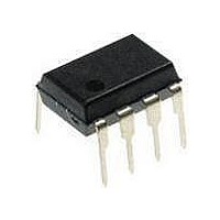
ATTINY12V-1PU Atmel, ATTINY12V-1PU Datasheet - Page 45

ATTINY12V-1PU
Manufacturer Part Number
ATTINY12V-1PU
Description
Microcontrollers (MCU) AVR 1K FLASH 64B EE 1.8V 1MHZ
Manufacturer
Atmel
Datasheet
1.ATTINY12V-1SI.pdf
(94 pages)
Specifications of ATTINY12V-1PU
Processor Series
ATTINY1x
Core
AVR8
Data Bus Width
8 bit
Program Memory Type
Flash
Program Memory Size
1 KB
Maximum Clock Frequency
1.2 MHz
Number Of Programmable I/os
6
Number Of Timers
1
Maximum Operating Temperature
+ 85 C
Mounting Style
Through Hole
Package / Case
PDIP-8
3rd Party Development Tools
EWAVR, EWAVR-BL
Minimum Operating Temperature
- 40 C
Package
8PDIP
Device Core
AVR
Family Name
ATtiny
Maximum Speed
1.2 MHz
Operating Supply Voltage
2.5|3.3|5 V
Interface Type
SPI
Operating Temperature
-40 to 85 °C
Lead Free Status / Rohs Status
Details
Analog Comparator
Register Description
Analog Comparator Control
and Status Register – ACSR
1006F–AVR–06/07
The Analog Comparator compares the input values on the positive input PB0 (AIN0) and
negative input PB1 (AIN1). When the voltage on the positive input PB0 (AIN0) is higher
than the voltage on the negative input PB1 (AIN1), the Analog Comparator Output
(ACO) is set (one). The comparator’s output can trigger a separate interrupt, exclusive
to the Analog Comparator. The user can select interrupt triggering on comparator output
rise, fall or toggle. A block diagram of the comparator and its surrounding logic is shown
in Figure 25.
Figure 25. Analog Comparator Block Diagram.
Note:
• Bit 7 - ACD: Analog Comparator Disable
When this bit is set (one), the power to the Analog Comparator is switched off. This bit
can be set at any time to turn off the Analog Comparator. When changing the ACD bit,
the Analog Comparator Interrupt must be disabled by clearing the ACIE bit in ACSR.
Otherwise an interrupt can occur when the bit is changed.
• Bit 6 - AINBG: Analog Comparator Bandgap Select in ATtiny12
In ATtiny12, when this bit is set, a fixed bandgap voltage of 1.22 ± 0.05V replaces the
normal input to the positive input (AIN0) of the comparator. When this bit is cleared, the
normal input pin PB0 is applied to the positive input of the comparator.
• Bit 6- Res: Reserved Bit in ATtiny11
This bit is a reserved bit in the ATtiny11 and will always read as zero.
• Bit 5 - ACO: Analog Comparator Output
ACO is directly connected to the comparator output.
(ATtiny12 ONLY)
Bit
$08
Read/Write
Initial Value
REFERENCE
INTERNAL
VOLTAGE
AINBG is only available in ATtiny12.
ACD
R/W
7
0
AINBG
MUX
(AINBG)
R(/W)
6
0
ACO
R
5
X
R/W
ACI
4
0
ACIE
R/W
3
0
R
2
0
-
ACIS1
ATtiny11/12
R/W
1
0
ACIS0
R/W
0
0
ACSR
45


