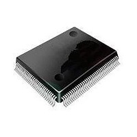
ST92F120V1Q7 STMicroelectronics, ST92F120V1Q7 Datasheet - Page 318

ST92F120V1Q7
Manufacturer Part Number
ST92F120V1Q7
Description
Microcontrollers (MCU) Flash 128K SPI/I2C
Manufacturer
STMicroelectronics
Datasheet
1.ST92F120V9Q7.pdf
(325 pages)
Specifications of ST92F120V1Q7
Data Bus Width
8 bit, 16 bit
Program Memory Type
Flash
Program Memory Size
128 KB
Data Ram Size
4 KB
Interface Type
I2C, SPI
Maximum Clock Frequency
24 MHz
Number Of Programmable I/os
77
Number Of Timers
5
Maximum Operating Temperature
+ 105 C
Mounting Style
SMD/SMT
Package / Case
PQFP-100
Minimum Operating Temperature
- 40 C
On-chip Adc
8 bit, 16 Channel
Lead Free Status / Rohs Status
No
Available stocks
Company
Part Number
Manufacturer
Quantity
Price
Company:
Part Number:
ST92F120V1Q7
Manufacturer:
ST
Quantity:
6 765
Part Number:
ST92F120V1Q7
Manufacturer:
ST
Quantity:
20 000
Part Number:
ST92F120V1Q7C
Manufacturer:
ST
Quantity:
20 000
Company:
Part Number:
ST92F120V1Q7DTR
Manufacturer:
MAXIM
Quantity:
2 854
- Current page: 318 of 325
- Download datasheet (3Mb)
ST92F120 - SUMMARY OF CHANGES
318/324
1
Rev.
1.3
Page Section
226
227
18
20
21
29
38
50
51
53
54
55
57
63
64
65
86
87
95
112
18
103
104
112
248
249
24
26
27
35
44
59
60
62
63
64
65
73
79
80
86
lowing
- Fig. 10: PAGE REGISTERS: replaced with PAGED REGISTERS
- Second col.
End of first col."...into four16 Kbytes pages.". Removed space.
End of second col.Chapter 3: cross ref updated
Replaced the Chapter 3 new doc specs Added a register and Section on protection
strategy).
Moved para. on register map to page 63
- A note in the picture added: "RAM addresses are repeated each 4 Kbytes inside
the segment 20h"
- FLASH OTP - 128 bytes: the starting address 210000h
Replaced the address with 211F80h
Same as Page 51
ZAD0 and ZAD1 removed and replaced with "Res."
Added detailed register map (7 pages)
Changed table
Changed 2 tables
Changed figure
WUIMU section revised (edited text throughout)
Changed figure: added 16 divider to CK128 input to STIM and P6.0 output with 8
div.
Changed figure: like previous page
Changed values in two tables
Added rows in second table. Changed RESET overbar to RESETN.
Changed P2.2 and P2.3 to Pure OD output, no WPU
In Column 2: “I/O pins are set to Bidirectional Weak-Pull-Up or High impedance in-
put. See Table of I/O port alternate functions.
Replaced ST92E120 with ST92E120/F120
In WAIT FOR INTERRUPT MODE item, removed the sentence:
"Under this mode,... (LP WFI)."
Created a new item: "LOW POWER WAIT FOR INTERRUPT" with the fol-
description:
"Combining SLOW Mode and Wait For Interrupt mode it is possible to
Second column: "Watchdog counter ..." sentence rewritten.
At the end of STOP MODE item, added:
"The counter is active only when the oscillation has already taken
Last sentence "A table of available...": removed.
Added registers for AD0 and AD1:
. AD0 - Page 63(3F) All registers from R240 to R255
. AD1 - Page 61(3D) All registers from R240 to R255
Note removed.
reduce the power consumption by more than 80%."
place: this means that 1-2 ms must be added to take into account of
the first phase of the oscillator restarting."
Main changes
12/16/97
Date
Related parts for ST92F120V1Q7
Image
Part Number
Description
Manufacturer
Datasheet
Request
R

Part Number:
Description:
8/16-bit Flash Mcu Family With Ram, Eeprom And J1850 Blpd
Manufacturer:
STMicroelectronics
Datasheet:

Part Number:
Description:
STMicroelectronics [RIPPLE-CARRY BINARY COUNTER/DIVIDERS]
Manufacturer:
STMicroelectronics
Datasheet:

Part Number:
Description:
STMicroelectronics [LIQUID-CRYSTAL DISPLAY DRIVERS]
Manufacturer:
STMicroelectronics
Datasheet:

Part Number:
Description:
BOARD EVAL FOR MEMS SENSORS
Manufacturer:
STMicroelectronics
Datasheet:

Part Number:
Description:
NPN TRANSISTOR POWER MODULE
Manufacturer:
STMicroelectronics
Datasheet:

Part Number:
Description:
TURBOSWITCH ULTRA-FAST HIGH VOLTAGE DIODE
Manufacturer:
STMicroelectronics
Datasheet:

Part Number:
Description:
Manufacturer:
STMicroelectronics
Datasheet:

Part Number:
Description:
DIODE / SCR MODULE
Manufacturer:
STMicroelectronics
Datasheet:

Part Number:
Description:
DIODE / SCR MODULE
Manufacturer:
STMicroelectronics
Datasheet:

Part Number:
Description:
Search -----> STE16N100
Manufacturer:
STMicroelectronics
Datasheet:

Part Number:
Description:
Search ---> STE53NA50
Manufacturer:
STMicroelectronics
Datasheet:

Part Number:
Description:
NPN Transistor Power Module
Manufacturer:
STMicroelectronics
Datasheet:


