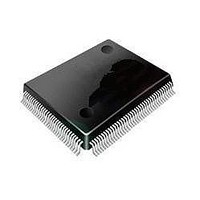
ST92F120V1Q7 STMicroelectronics, ST92F120V1Q7 Datasheet - Page 44

ST92F120V1Q7
Manufacturer Part Number
ST92F120V1Q7
Description
Microcontrollers (MCU) Flash 128K SPI/I2C
Manufacturer
STMicroelectronics
Datasheet
1.ST92F120V9Q7.pdf
(325 pages)
Specifications of ST92F120V1Q7
Data Bus Width
8 bit, 16 bit
Program Memory Type
Flash
Program Memory Size
128 KB
Data Ram Size
4 KB
Interface Type
I2C, SPI
Maximum Clock Frequency
24 MHz
Number Of Programmable I/os
77
Number Of Timers
5
Maximum Operating Temperature
+ 105 C
Mounting Style
SMD/SMT
Package / Case
PQFP-100
Minimum Operating Temperature
- 40 C
On-chip Adc
8 bit, 16 Channel
Lead Free Status / Rohs Status
No
Available stocks
Company
Part Number
Manufacturer
Quantity
Price
Company:
Part Number:
ST92F120V1Q7
Manufacturer:
ST
Quantity:
6 765
Part Number:
ST92F120V1Q7
Manufacturer:
ST
Quantity:
20 000
Part Number:
ST92F120V1Q7C
Manufacturer:
ST
Quantity:
20 000
Company:
Part Number:
ST92F120V1Q7DTR
Manufacturer:
MAXIM
Quantity:
2 854
- Current page: 44 of 325
- Download datasheet (3Mb)
ST92F120 - SINGLE VOLTAGE FLASH & EEPROM
REGISTER DESCRIPTION (Cont’d)
Bit 2 = WFIS: Wait For Interrupt Status.
If this bit is reset, the WFI instruction puts the
Flash macrocell in Stand-by mode (immediate
read possible, but higher consumption: 100 A); if
it is set, the WFI instruction puts the Flash macro-
cell in Power-Down mode (recovery time of 10 s
needed before reading, but lower consumption:
10 A). The Stand-by mode or the Power-Down
mode will be entered only at the end of any current
Flash or EEPROM write operation.
In the same way following an HALT or a STOP in-
struction, the Memory enters Power-Down mode
only after the completion of any current write oper-
ation.
0: Flash in Standby mode on WFI
1: Flash in Power-Down mode on WFI
Note: HALT or STOP mode can be exited without
problems, but the user should take care when ex-
iting WFI Power Down mode. If WFIS is set, the
user code must reset the XT_DIV16 bit in the
R242 register (page 55) before executing the WFI
instruction. When exiting WFI mode, this gives the
Flash enough time to wake up before the interrupt
vector fetch.
Bit 1 = FEIEN: Flash & EEPROM Interrupt enable .
This bit selects the source of interrupt channel
INTx between the external interrupt pin and the
Flash/EEPROM End of Write interrupt. Refer to
the Interrupt chapter for the channel number.
0: External interrupt enabled
1: Flash & EEPROM Interrupt enabled
44/324
9
Bit 0 = EBUSY: EEPROM Busy (Read Only).
This bit is automatically set during a Page Update
operation when the first address to be modified is
latched in the EEPROM memory, or during Chip
Erase operation when bit EWMS is set. At the end
of the write operation or during a Sector Erase
Suspend this bit is automatically reset and the
memory returns to read mode. When this bit is set
every read access to the EEPROM memory will
output invalid data (FFh equivalent to a NOP in-
struction), while every write access to the EEP-
ROM memory will be ignored. At the end of the
write operation this bit is automatically reset and
the memory returns to read mode. Bit EBUSY re-
mains high for a maximum of 10ms after Power-
Up and when exiting Power-Down mode, meaning
that the EEPROM memory is not yet ready to be
accessed.
0: EEPROM not busy
1: EEPROM busy
Related parts for ST92F120V1Q7
Image
Part Number
Description
Manufacturer
Datasheet
Request
R

Part Number:
Description:
8/16-bit Flash Mcu Family With Ram, Eeprom And J1850 Blpd
Manufacturer:
STMicroelectronics
Datasheet:

Part Number:
Description:
STMicroelectronics [RIPPLE-CARRY BINARY COUNTER/DIVIDERS]
Manufacturer:
STMicroelectronics
Datasheet:

Part Number:
Description:
STMicroelectronics [LIQUID-CRYSTAL DISPLAY DRIVERS]
Manufacturer:
STMicroelectronics
Datasheet:

Part Number:
Description:
BOARD EVAL FOR MEMS SENSORS
Manufacturer:
STMicroelectronics
Datasheet:

Part Number:
Description:
NPN TRANSISTOR POWER MODULE
Manufacturer:
STMicroelectronics
Datasheet:

Part Number:
Description:
TURBOSWITCH ULTRA-FAST HIGH VOLTAGE DIODE
Manufacturer:
STMicroelectronics
Datasheet:

Part Number:
Description:
Manufacturer:
STMicroelectronics
Datasheet:

Part Number:
Description:
DIODE / SCR MODULE
Manufacturer:
STMicroelectronics
Datasheet:

Part Number:
Description:
DIODE / SCR MODULE
Manufacturer:
STMicroelectronics
Datasheet:

Part Number:
Description:
Search -----> STE16N100
Manufacturer:
STMicroelectronics
Datasheet:

Part Number:
Description:
Search ---> STE53NA50
Manufacturer:
STMicroelectronics
Datasheet:

Part Number:
Description:
NPN Transistor Power Module
Manufacturer:
STMicroelectronics
Datasheet:


