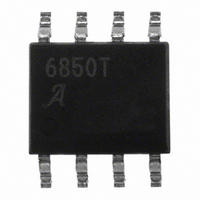
A6850KLTR-T Allegro Microsystems Inc, A6850KLTR-T Datasheet

A6850KLTR-T
Specifications of A6850KLTR-T
Available stocks
Related parts for A6850KLTR-T
A6850KLTR-T Summary of contents
Page 1
Features and Benefits ▪ 4.75 to 26.5 V operation ▪ Low V -to-V voltage drop IN OUT ▪ current sense feedback 10 ▪ Survive short-to-battery and short-to-ground faults ▪ Survive 40 V load dump ▪ >4 kV ESD ...
Page 2
... The A6850 eliminates the need for the external series shunt resistor in Hall device applications by incorporating an integrated current mirror which reports the Hall IC supply current as a the SENSE1 or SENSE2 output pin. A low current Sleep mode is Selection Guide Part Number A6850KLTR-T 13-in. reel, 3000 pieces/reel Absolute Maximum Ratings Characteristic Supply Voltage Output Voltage ...
Page 3
A6850 ELECTRICAL CHARACTERISTICS at T Characteristics Supply Input Voltage Range Supply Input Quiescent Current 1 Power-Up Time Output Rise Time 2 2 Output Fall Time 2 Enable Delay Time 2 Disable Delay Time OUTPUTx Source Resistance OUTPUTx Leakage Current SENSEx ...
Page 4
A6850 0 mA 10% OUTPUTx 90% current 90% SENSEx voltage 10 Figure 1. Signal Channel Timing, ENABLE1 = ENABLE1 = High, R 50% ENABLEx Voltage OUTPUTx Current 50% SENSEx Voltage 0 V Figure 2. ...
Page 5
A6850 SENSE Pin Outputs The A6850 divides the OUTPUTx pin current by 10 and mirrors it onto the corresponding SENSEx pin. Putting sense resistors, RSENSE , from these pins to ground will create a voltage that can be read by ...
Page 6
A6850 Signal and Enable delays When ENABLEx = 1, current signals applied to the OUTPUTx pins will appear scaled and delayed on the SENSEx pins. The transfer characteristic can be considered that of a low pass filter. The response time ...
Page 7
A6850 T can be estimated by calculating the power dissipation (P J the A6850. To calculate INQ – V – OUTPUT1 OUTPUT1 OUTPUT2 – V – SENSE1 ...
Page 8
A6850 Two-Wire Hall IC Interfacing When voltage is applied to two-wire Hall effect ICs, current flows within one of two narrow ranges. Any current level not within these ranges indicates a fault condition. Signal and Fault Table Condition OUTPUT Pin ...
Page 9
A6850 Mechanical Switch Interfacing The A6850 can be used as an interface between mechanical switches, set in a switch-to-ground configuration, and a low voltage microprocessor. A series resistor must be placed in the circuit to limit current when the mechanical ...
Page 10
A6850 Ganging SENSE1 and SENSE2 In certain applications both outputs may be read with a single ADC channel. The OUTPUTx loads are enabled by alternatively activating ENABLEx. In fact, both ENABLE1 Vcc Controller Figure 7. Outline of ganged configuration V ...
Page 11
A6850 Protection from EMI Transients generated by electromagnetic interference (EMI) can disturb operation of the A6850 or add unwanted noise to the signals being processed. The scheme shown in figure 9 illustrates possible supply decou- pling and signal filtering options. ...
Page 12
A6850 4.90 ±0. 0.20 C 0.41 ±0.10 Copyright ©2006-2011, Allegro MicroSystems, Inc. Allegro MicroSystems, Inc. reserves the right to make, from time to time, such de par tures from the detail spec ...


