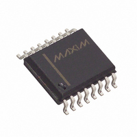
DS2175S/T&R Maxim Integrated Products, DS2175S/T&R Datasheet

DS2175S/T&R
Specifications of DS2175S/T&R
Related parts for DS2175S/T&R
DS2175S/T&R Summary of contents
Page 1
FEATURES Rate buffer for T1 and CEPT transmission systems Synchronizes loop–timed and system timed data streams on frame boundaries Ideal for T1 (1.544 MHz) to CEPT (2.048 MHz), CEPT to T1 interfaces Supports parallel and serial backplanes Buffer depth ...
Page 2
DS2175 BLOCK DIAGRAM Figure DS2175 ...
Page 3
PIN SYMBOL TYPE 1 RCLKSEL 2 RCLK 3 RSER 4 RMSYNC 5 FSD 6 SLIP 7 ALN SCLKSEL SCHCLK 12 SFSYNC 13 SMSYNC 14 SSER 15 SYSCLK PCM BUFFER ...
Page 4
SLIP CORRECTION CAPABILITY The 2–frame buffer depth is adequate for T–carrier and CEPT applications where short term jitter synchronization, rather than correction of significant frequency differences, is required. The DS2175 provides an ideal balance between total delay (less than 250 ...
Page 5
RECEIVE SIDE TIMING (RCLK = 1.544 MHz) Figure 2 RECEIVE SIDE TIMING (RCLK = 2.048 MHz) Figure 3 NOTES: 1. All channel data is passed through the elastic store in 2.048 MHz system side applications (SCLKSEL = 1); 2. Data ...
Page 6
SYSTEM MULTIFRAME BOUNDARY TIMING (SYSCLK = 2.048 MHz) Figure 5 NOTES 2.048 MHz receive side applications (RCLKSEL=1), all channel data is passed through the elastic store 1.544 MHz receive side applications (RCLKSEL=0), all channel data is ...
Page 7
RECOMMENDED DC OPERATING CONDITIONS PARAMETER SYMBOL Logic 1 Logic 0 Supply CAPACITANCE PARAMETER SYMBOL Input Capacitance Output Capacitance DC ELECTRICAL CHARACTERISTICS PARAMETER SYMBOL Supply Current Input Leakage Output Current @ 2.4V Output Current @ 0.4V NOTES: 1. SYSCLK = RCLK ...
Page 8
AC ELECTRICAL CHARACTERISTICS PARAMETER RCLK Period RCLK, SYSCLK Rise and Fall Times RCLK Pulse Width SYSCLK Pulse Width SYSCLK Period RMSYNC Setup to RCLK Falling SFSYNC Setup to SYSCLK Falling RMSYNC, SFSYNC, ALN Pulse Width RSER Setup from RCLK Falling ...
Page 9
RECEIVE AC TIMING DIAGRAM Figure 6 SYSTEM AC TIMING DIAGRAM Figure DS2175 ...
Page 10
DS2175 T1/CEPT ELASTIC STORE PKG DIM A IN. B IN. C IN. D IN. E IN. F IN. G IN. H IN. J IN DS2175 16-PIN MIN MAX 0.740 0.780 0.240 0.260 0.120 0.140 0.300 ...
Page 11
DS2175S T1/CEPT ELASTIC STORE PKG DIM A IN. B IN. C IN. E IN. F IN. G IN. H IN. J IN. K IN DS2175 16-PIN MIN MAX 0.402 0.412 0.290 0.300 0.089 0.095 0.004 ...
Page 12
DATA SHEET REVISION SUMMARY The following represent the key differences between 04/19/95 and 06/13/97 version of the DS2175 data sheet. Please review this summary carefully. 1. SYNC/CLOCK Relationship in timing diagram DS2175 ...


