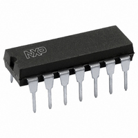
HEF4016BP,652 NXP Semiconductors, HEF4016BP,652 Datasheet - Page 3

HEF4016BP,652
Manufacturer Part Number
HEF4016BP,652
Description
IC SWITCH QUAD 2X1 14DIP
Manufacturer
NXP Semiconductors
Series
4000Br
Specifications of HEF4016BP,652
Package / Case
14-DIP (0.300", 7.62mm)
Function
Switch
Circuit
4 x 2:1
On-state Resistance
350 Ohm
Current - Supply
4µA
Operating Temperature
-40°C ~ 85°C
Mounting Type
Through Hole
Switch Configuration
SPST
On Resistance (max)
8000 Ohm (Typ) @ 5 V
On Time (max)
80 ns @ 5 V
Off Time (max)
130 ns @ 5 V
Supply Voltage (max)
15.5 V
Supply Voltage (min)
4.5 V
Maximum Power Dissipation
400 mW
Maximum Operating Temperature
+ 85 C
Mounting Style
Through Hole
Minimum Operating Temperature
- 40 C
Lead Free Status / RoHS Status
Lead free / RoHS Compliant
Lead Free Status / RoHS Status
Lead free / RoHS Compliant, Lead free / RoHS Compliant
Other names
568-3079-5
933282410652
HEF4016BPN
933282410652
HEF4016BPN
Philips Semiconductors
RATINGS
Limiting values in accordance with the Absolute Maximum System (IEC 134)
DC CHARACTERISTICS
T
January 1995
Power dissipation per switch
For other RATINGS see Family Specifications
ON resistance
ON resistance
ON resistance
‘ ’ ON resistance
between any two
channels
Quiescent
Input leakage
OFF-state leakage
E
E
amb
n
n
Quadruple bilateral switches
device
current
current at E
current, any
channel OFF
voltage LOW
voltage HIGH
PARAMETER
PARAMETER
input
input
= 25 C; V
n
SS
= 0 V (unless otherwise specified)
V
V
V
DD
10
15
10
15
10
15
10
15
V
DD
10
15
15
10
15
10
15
10
15
5
5
5
5
5
5
5
5
R
R
R
SYMBOL
I
I
V
V
R
DD
OZ
SYMBOL
ON
ON
ON
IL
IH
I
ON
IN
MIN. MAX. MIN. MAX. MIN. MAX.
11,0
3,5
7,0
TYP.
8000
230
140
170
200
115
40
65
50
95
75
15
10
1,0
2,0
4,0
1,5
3,0
4,0
3
MAX.
11,0
690
350
425
195
145
515
285
220
T
3,5
7,0
amb
25
( C)
300
200
1,0
4,0
2,0
4,0
1,5
3,0
UNIT
11,0
P
3,5
7,0
E
E
E
E
n
n
n
n
85
1000
15,0
30,0
at V
at V
at V
at V
1,5
3,0
4,0
7,5
max.
IH
IH
IH
IH
; V
; V
; V
; V
nA
nA
nA
nA
V
V
V
V
V
V
UNIT
A
A
A
is
is
is
is
CONDITIONS
= 0 to V
= V
= V
= 0 to V
SS
DD
100
V
input combinations;
V
E
E
V
V
switch OFF; see
Fig.9 for I
low-impedance
between Y and Z (ON
condition)
see R
SS
I
n
n
is
os
Product specification
; see Fig.4
; see Fig.4
= V
at V
at V
HEF4016B
= V
DD
DD
= V
= 0; all valid
CONDITION
ON
SS
; see Fig.4
; see Fig.4
SS
SS
IL
DD
mW
;
or V
switch
OZ
or V
or V
or V
gates
DD
DD
DD
SS
;


