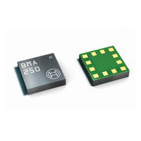
BMA250 Bosch Sensortec, BMA250 Datasheet - Page 11

BMA250
Manufacturer Part Number
BMA250
Description
3-AXIS ACCELEROMETER DIGITAL I/F
Manufacturer
Bosch Sensortec
Series
-r
Specifications of BMA250
Featured Product
BMA250 - Digital, Triaxial Acceleration Sensor
Axis
X, Y, Z
Acceleration Range
±2g, 4g, 8g, 16g
Sensitivity
256LSB/g, 128LSB/g, 64LSB/g, 16LSB/g
Voltage - Supply
1.62 V ~ 3.6 V
Output Type
I²C™, SPI™
Bandwidth
8Hz ~ 1kHz
Interface
I²C, SPI
Mounting Type
Surface Mount
Package / Case
12-VQFN
Lead Free Status / Rohs Status
Lead free / RoHS Compliant
For Use With
828-1024 - BMA250 DAUGHTERCARD FOR DEV KIT
Other names
828-1023-2
Available stocks
Company
Part Number
Manufacturer
Quantity
Price
Part Number:
BMA250
Manufacturer:
BOSCH/博世
Quantity:
20 000
Company:
Part Number:
BMA250E
Manufacturer:
AME
Quantity:
12 000
Part Number:
BMA250E
Manufacturer:
BOSCH/博世
Quantity:
20 000
Part Number:
BMA250E(F)
Manufacturer:
BOSCH/博世
Quantity:
20 000
Part Number:
BMA250E-F
Manufacturer:
BOSCH/博世
Quantity:
20 000
Company:
Part Number:
BMA250EF
Manufacturer:
TE
Quantity:
30 000
Part Number:
BMA250EF
Manufacturer:
BOSCH/博世
Quantity:
20 000
both supply voltages. In case the I²C interface shall be used, a direct electrical connection
between V
(see section 4.2 Operational modes).
4.2 Operational modes
Depending on the configuration the BMA250 is able to operate in two different operational
modes:
The selection of the operational mode is done during start-up or reset by the state of the PS pin.
If PS is floating, the dedicated mode is selected. A defined digital state selects the general
mode. All pads are in input mode (no output driver active) during the start-up sequence until the
operational mode and, in case of the general mode, the interface type is selected. The start-up
sequence is run after power-up and after reset.
Figure 2 illustrates the selection of the different operational modes:
Rev. 1.0
© Bosch Sensortec GmbH reserves all rights even in the event of industrial property rights. We reserve all rights of disposal such
as copying and passing on to third parties. BOSCH and the symbol are registered trademarks of Robert Bosch GmbH, Germany.
Note: Specifications within this document are subject to change without notice.
General mode: The device is acting as a slave on a digital interface (SPI or I²C) and is
controlled by the external bus master (e.g. μC). The master gets measurement data and
status information from the device through the digital interface. In particular, the master
can configure the interrupt controller and read out the interrupt status registers.
Moreover, it can freely configure and use the two interrupt pins (INT1, INT2). Several
interrupts may be enabled in parallel.
Dedicated mode: The dedicated mode allows the sensor to be operated as a stand-
alone device in a simple μC-less system without abandon of the interrupt functionality.
No digital interface is needed and, as a consequence, no measurement data can be
read from the device. Instead of the digital interface the internal interrupt engine with its
default setting is used. The interrupt status is mapped onto dedicated output pins. One
out of three different sub-modes can be chosen: A) orientation recognition, B) tap
sensing or C) slope (any-motion) detection. Only one interrupt at a time can be
assigned.
DDIO
supply and the PS pin is needed in order to ensure reliable protocol selection
Figure 2: Operational mode selection
Page 11 / not for publishing
Data sheet
BMA250
Bosch Sensortec
03 March 2011


