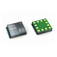
BMA250 Bosch Sensortec, BMA250 Datasheet - Page 12

BMA250
Manufacturer Part Number
BMA250
Description
3-AXIS ACCELEROMETER DIGITAL I/F
Manufacturer
Bosch Sensortec
Series
-r
Specifications of BMA250
Featured Product
BMA250 - Digital, Triaxial Acceleration Sensor
Axis
X, Y, Z
Acceleration Range
±2g, 4g, 8g, 16g
Sensitivity
256LSB/g, 128LSB/g, 64LSB/g, 16LSB/g
Voltage - Supply
1.62 V ~ 3.6 V
Output Type
I²C™, SPI™
Bandwidth
8Hz ~ 1kHz
Interface
I²C, SPI
Mounting Type
Surface Mount
Package / Case
12-VQFN
Lead Free Status / Rohs Status
Lead free / RoHS Compliant
For Use With
828-1024 - BMA250 DAUGHTERCARD FOR DEV KIT
Other names
828-1023-2
Available stocks
Company
Part Number
Manufacturer
Quantity
Price
Part Number:
BMA250
Manufacturer:
BOSCH/博世
Quantity:
20 000
Company:
Part Number:
BMA250E
Manufacturer:
AME
Quantity:
12 000
Part Number:
BMA250E
Manufacturer:
BOSCH/博世
Quantity:
20 000
Part Number:
BMA250E(F)
Manufacturer:
BOSCH/博世
Quantity:
20 000
Part Number:
BMA250E-F
Manufacturer:
BOSCH/博世
Quantity:
20 000
Company:
Part Number:
BMA250EF
Manufacturer:
TE
Quantity:
30 000
Part Number:
BMA250EF
Manufacturer:
BOSCH/博世
Quantity:
20 000
4.2.1 General mode
A defined digital state at the PS pin selects the general mode. Its polarity determines the kind of
interface to be used:
4.2.2 Dedicated mode (μC-less or stand-alone mode)
The dedicated mode operates with pre-defined settings of the interrupt engine in order to
generate the motion-triggered interrupt-signals, i.e. bandwidth, sleep time, low-power mode,
threshold, and hysteresis are use case optimized. Nevertheless some minor configurations can
be selected by the user. The dedicated mode is entered if the device is connected according to
table 3. During the start-up / power on sequence the PS pin (#11) must float.
Table 3: Entering and operating dedicated mode
Depending on the configuration of the other device pins according to table 4 the corresponding
sub-mode of the dedicated mode is entered. In table 4 and table 5 the unshaded entries
represent necessary input values for the corresponding sub-mode selection while the shaded
entries represent corresponding output parameters of the events to be detected.
Table 4: Sub-mode selection and specific outputs of the dedicated mode
Table 5 contains state and description details of the parameters introduced in table 4. Unshaded
entries represent input values to be set, shaded entries represent output parameters to be
detected.
Rev. 1.0
© Bosch Sensortec GmbH reserves all rights even in the event of industrial property rights. We reserve all rights of disposal such
as copying and passing on to third parties. BOSCH and the symbol are registered trademarks of Robert Bosch GmbH, Germany.
Note: Specifications within this document are subject to change without notice.
Sub-Mode
Orientation
Tap
Slope
VDDIO
Pin#3
V
PS = GND
PS = V
PS = float
DDIO
DDIO
orient1-detect
double-detect
output
output
Pin#1
GND
SDO
enables the digital SPI interface
enables the digital I²C interface
enables the dedicated mode
Pin#4
NC
NC
orient0-detect
motion-detect
single-detect
output
output
output
Pin#2
SDx
Page 12 / not for publishing
Pin#7
VDD
V
DD
Data sheet
BMA250
orient2-detect
output
Pin#5
INT1
GND
V
DD
GNDIO
Pin#8
GND
flat-detect
tap type
output
select
Pin#6
INT2
GND
Pin#9
GND
GND
orient sleep
slope sleep
tap sleep
Pin#10
select
select
select
CSB
Bosch Sensortec
03 March 2011
Pin#11
float
Pin#12
GND
PS
SCx
V
V
DD
DD


