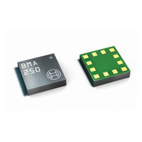
BMA250 Bosch Sensortec, BMA250 Datasheet - Page 14

BMA250
Manufacturer Part Number
BMA250
Description
3-AXIS ACCELEROMETER DIGITAL I/F
Manufacturer
Bosch Sensortec
Series
-r
Specifications of BMA250
Featured Product
BMA250 - Digital, Triaxial Acceleration Sensor
Axis
X, Y, Z
Acceleration Range
±2g, 4g, 8g, 16g
Sensitivity
256LSB/g, 128LSB/g, 64LSB/g, 16LSB/g
Voltage - Supply
1.62 V ~ 3.6 V
Output Type
I²C™, SPI™
Bandwidth
8Hz ~ 1kHz
Interface
I²C, SPI
Mounting Type
Surface Mount
Package / Case
12-VQFN
Lead Free Status / Rohs Status
Lead free / RoHS Compliant
For Use With
828-1024 - BMA250 DAUGHTERCARD FOR DEV KIT
Other names
828-1023-2
Available stocks
Company
Part Number
Manufacturer
Quantity
Price
Part Number:
BMA250
Manufacturer:
BOSCH/博世
Quantity:
20 000
Company:
Part Number:
BMA250E
Manufacturer:
AME
Quantity:
12 000
Part Number:
BMA250E
Manufacturer:
BOSCH/博世
Quantity:
20 000
Part Number:
BMA250E(F)
Manufacturer:
BOSCH/博世
Quantity:
20 000
Part Number:
BMA250E-F
Manufacturer:
BOSCH/博世
Quantity:
20 000
Company:
Part Number:
BMA250EF
Manufacturer:
TE
Quantity:
30 000
Part Number:
BMA250EF
Manufacturer:
BOSCH/博世
Quantity:
20 000
4.3 Power modes
The BMA250 has three different power modes. Besides normal mode, which represents the fully
operational state of the device, there are two special energy saving modes: low-power mode
and suspend mode.
The possible transitions between the power modes are illustrated in figure 3:
In normal mode, all parts of the electronic circuit are held powered-up and data acquisition is
performed continuously.
In contrast to this, in suspend mode the whole analog part, oscillators included, is powered
down. No data acquisition is performed, the only supported operations are reading registers
(latest acceleration data are kept) and writing to the (0x11) suspend bit or (0x14) softreset
register. Suspend mode is entered (left) by writing ´1´ (´0´) to the (0x11) suspend bit.
In low-power mode, the device is periodically switching between a sleep phase and a wake-up
phase. The wake-up phase essentially corresponds to operation in normal mode with complete
power-up of the circuitry. During the sleep phase the analog part except the oscillators is
powered down. Low-power mode is entered (left) by writing ´1´ (´0´) to the (0x11) lowpower_en
bit.
During the wake-up phase the number of samples required by any enabled interrupt is
processed. If an interrupt is detected, the device stays in the wake-up phase as long as the
interrupt condition endures (non-latched interrupt), or until the latch time expires (temporary
interrupt), or until the interrupt is reset (latched interrupt). If no interrupt is detected, the device
enters the sleep phase.
The duration of the sleep phase is set by the (0x11) sleep_dur bits as shown in the following
table:
Rev. 1.0
© Bosch Sensortec GmbH reserves all rights even in the event of industrial property rights. We reserve all rights of disposal such
as copying and passing on to third parties. BOSCH and the symbol are registered trademarks of Robert Bosch GmbH, Germany.
Note: Specifications within this document are subject to change without notice.
Figure 3: Power mode transition diagram
Low-Power
Power off
Mode
Page 14 / not for publishing
Data sheet
BMA250
Suspend
Normal
Mode
Mode
Bosch Sensortec
03 March 2011


