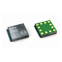
BMA250 Bosch Sensortec, BMA250 Datasheet - Page 26

BMA250
Manufacturer Part Number
BMA250
Description
3-AXIS ACCELEROMETER DIGITAL I/F
Manufacturer
Bosch Sensortec
Series
-r
Specifications of BMA250
Featured Product
BMA250 - Digital, Triaxial Acceleration Sensor
Axis
X, Y, Z
Acceleration Range
±2g, 4g, 8g, 16g
Sensitivity
256LSB/g, 128LSB/g, 64LSB/g, 16LSB/g
Voltage - Supply
1.62 V ~ 3.6 V
Output Type
I²C™, SPI™
Bandwidth
8Hz ~ 1kHz
Interface
I²C, SPI
Mounting Type
Surface Mount
Package / Case
12-VQFN
Lead Free Status / Rohs Status
Lead free / RoHS Compliant
For Use With
828-1024 - BMA250 DAUGHTERCARD FOR DEV KIT
Other names
828-1023-2
Available stocks
Company
Part Number
Manufacturer
Quantity
Price
Part Number:
BMA250
Manufacturer:
BOSCH/博世
Quantity:
20 000
Company:
Part Number:
BMA250E
Manufacturer:
AME
Quantity:
12 000
Part Number:
BMA250E
Manufacturer:
BOSCH/博世
Quantity:
20 000
Part Number:
BMA250E(F)
Manufacturer:
BOSCH/博世
Quantity:
20 000
Part Number:
BMA250E-F
Manufacturer:
BOSCH/博世
Quantity:
20 000
Company:
Part Number:
BMA250EF
Manufacturer:
TE
Quantity:
30 000
Part Number:
BMA250EF
Manufacturer:
BOSCH/博世
Quantity:
20 000
BMA250
Bosch Sensortec
Data sheet
The threshold is set with the value of register (0x28) slope_th. 1 LSB of (0x28) slope_th
corresponds to 1 LSB of acceleration data. Therefore, an increment of (0x28) slope_th is 3.91
mg in 2g-range (7.81 mg in 4g-range, 15.6 mg in 8g-range and 31.3 mg in 16g-range). And the
maximum value is 996 mg in 2g-range (1.99g in 4g-range, 3.98g in 8g-range and 7.97g in 16g-
range).
The time difference between the successive acceleration signals depends on the selected
bandwidth and equates to 1/(2*bandwidth) (Δt=1/(2*bw)). In order to suppress failure signals,
the interrupt is only generated (cleared) if a certain number N of consecutive slope data points is
larger (smaller) than the slope threshold given by (0x28) slope_th. This number is set by the
(0x27) slope_dur bits. It is N = (0x27) slope_dur + 1 for (0x27).
Example: (0x27) slope_dur = 00b, …, 11b = 1decimal, …, 4decimal
4.8.5.1 Enabling (disabling) for each axis
Any-motion detection can be enabled (disabled) for each axis separately by writing ´1´ (´0´) to
bits (0x16) slope_en_x, (0x16) slope_en_y, (0x16) slope_en_z. The criteria for any-motion
detection are fulfilled and the slope interrupt is generated if the slope of any of the enabled axes
exceeds the threshold (0x28) slope_th for [(0x27) slope_dur +1] consecutive times. As soon as
the slopes of all enabled axes fall or stay below this threshold for [(0x27) slope_dur +1]
consecutive times the interrupt is cleared unless interrupt signal is latched.
4.8.5.2 Axis and sign information of any motion interrupt
The interrupt status is stored in bit (0x09) slope_int. The any-motion interrupt supplies additional
information about the detected slope. The axis which triggered the interrupt is given by that one
of bits (0x0B) slope_first_x, (0x0B) slope_first_y, (0x0B) slope_first_z that contains a ´1´. The
sign of the triggering slope is held in bit (0x0B) slope_sign. If (0x0B) slope_sign = ´0´ (´1´), the
sign is positive (negative).
4.8.5.3 Serial interface and dedicated wake-up mode
When serial interface is active, any-motion detection logic is enabled if any of the axis specific
(0x16) slope_en_... register bits are set. To disable the any-motion interrupt, clear all the axis
specific (0x16) slope_en_... bits.
In the dedicated wake-up mode (see chapter 4.2.2), all three axes are enabled for any-motion
detection whether the individual axis enable bits are set or not.
4.8.6 Tap sensing
Tap sensing has a functional similarity with a common laptop touch-pad or clicking keys of a
computer mouse. A tap event is detected if a pre-defined slope of the acceleration of at least
one axis is exceeded. Two different tap events are distinguished: A ‘single tap’ is a single event
within a certain time, followed by a certain quiet time. A ‘double tap’ consists of a first such
event followed by a second event within a defined time frame.
Only one of the tap interrupts can be enabled at the same time. Single tap interrupt is enabled
(disabled) by writing ´1´ (´0´) to bit (0x16) s_tap_en. Double tap interrupt is enabled (disabled)
by writing ´1´ (´0´) to bit (0x16) d_tap_en. If one tries to enable both interrupts by writing ´1´ to
Rev. 1.0
Page 26 / not for publishing
03 March 2011
© Bosch Sensortec GmbH reserves all rights even in the event of industrial property rights. We reserve all rights of disposal such
as copying and passing on to third parties. BOSCH and the symbol are registered trademarks of Robert Bosch GmbH, Germany.
Note: Specifications within this document are subject to change without notice.


