BMA250 Bosch Sensortec, BMA250 Datasheet - Page 35
BMA250
Manufacturer Part Number
BMA250
Description
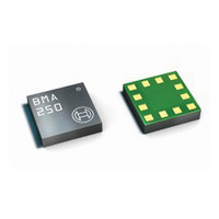
3-AXIS ACCELEROMETER DIGITAL I/F
Manufacturer
Bosch Sensortec
Series
-r
Specifications of BMA250
Featured Product
BMA250 - Digital, Triaxial Acceleration Sensor
Axis
X, Y, Z
Acceleration Range
±2g, 4g, 8g, 16g
Sensitivity
256LSB/g, 128LSB/g, 64LSB/g, 16LSB/g
Voltage - Supply
1.62 V ~ 3.6 V
Output Type
I²C™, SPI™
Bandwidth
8Hz ~ 1kHz
Interface
I²C, SPI
Mounting Type
Surface Mount
Package / Case
12-VQFN
Lead Free Status / Rohs Status
Lead free / RoHS Compliant
For Use With
828-1024 - BMA250 DAUGHTERCARD FOR DEV KIT
Other names
828-1023-2
Available stocks
Company
Part Number
Manufacturer
Quantity
Price

Part Number:
BMA250
Manufacturer:
BOSCH/博世
Quantity:
20 000
Company:
Part Number:
BMA250E
Manufacturer:
AME
Quantity:
12 000
Part Number:
BMA250E
Manufacturer:
BOSCH/博世
Quantity:
20 000
Part Number:
BMA250E(F)
Manufacturer:
BOSCH/博世
Quantity:
20 000
Part Number:
BMA250E-F
Manufacturer:
BOSCH/博世
Quantity:
20 000
Company:
Part Number:
BMA250EF
Manufacturer:
TE
Quantity:
30 000
Part Number:
BMA250EF
Manufacturer:
BOSCH/博世
Quantity:
20 000


BMA250
Bosch Sensortec
Data sheet
time defined by the (0x25) high_dur register. In bit (0x09) high_int the interrupt status is stored.
The relation between the content of (0x25) high_dur and the actual delay of the interrupt
generation is delay [ms] = [(0x22) low_dur + 1] • 2 ms. Therefore, possible delay times range
from 2 ms to 512 ms.
4.8.10.1 Axis and sign information of high-g interrupt
The axis which triggered the interrupt is indicated by bits (0x0C) high_first_x, (0x0C)
high_first_y, and (0x0C) high_first_z. The bit corresponding to the triggering axis contains a ´1´
while the other bits hold a ´0´. These bits are cleared together with clearing the interrupt status.
The sign of the triggering acceleration is stored in bit (0x0C) high_sign. If (0x0C) high_sign = ´0´
(´1´), the sign is positive (negative).
5. Register description
5.1 General remarks
The entire communication with the device is performed by reading from and writing to registers
(exception: dedicated mode, see chapter 4.2.2). Registers have a width of 8 bits; they are
mapped to a common space of 64 addresses from (0x00) up to (0x3F). Within the used range
there are several registers which are either completely or partially marked as ‘reserved’. Any
reserved bit is ignored when it is written and no specific value is guaranteed when read. It is
recommended not to use registers at all which are completely marked as ‘reserved’. Further-
more it is recommended to mask out (logical and with zero) reserved bits of registers which are
partially marked as reserved.
Registers with addresses from (0x00) up to (0x0E) are read-only. Any attempt to write to these
registers is ignored. There are bits within some registers that connected with an action to be
done and, therefore, are intended for write-only access, e. g. (0x21) reset_int or the entire
(0x14) softreset register. Such bits always give ´0´ when read.
Rev. 1.0
Page 35 / not for publishing
03 March 2011
© Bosch Sensortec GmbH reserves all rights even in the event of industrial property rights. We reserve all rights of disposal such
as copying and passing on to third parties. BOSCH and the symbol are registered trademarks of Robert Bosch GmbH, Germany.
Note: Specifications within this document are subject to change without notice.
Related parts for BMA250
Image
Part Number
Description
Manufacturer
Datasheet
Request
R

Part Number:
Description:
DEVELOPMENT BOARD FOR SENSOR ICS
Manufacturer:
Bosch Sensortec

Part Number:
Description:
BMA150 DAUGHTERCARD FOR DEV KIT
Manufacturer:
Bosch Sensortec
Datasheet:

Part Number:
Description:
BMA140 DAUGHTERCARD FOR DEV KIT
Manufacturer:
Bosch Sensortec
Datasheet:

Part Number:
Description:
BMA020 DAUGHTERCARD FOR DEV KIT
Manufacturer:
Bosch Sensortec

Part Number:
Description:
BMA020 TRIBOX DEMO BOARD W/USB
Manufacturer:
Bosch Sensortec

Part Number:
Description:
BMA150 TRIBOX DEMO BOARD W/USB
Manufacturer:
Bosch Sensortec
Datasheet:

Part Number:
Description:
BMA145 DAUGHTERCARD FOR DEV KIT
Manufacturer:
Bosch Sensortec
Datasheet:

Part Number:
Description:
DAUGHTERCARD FOR DEV KIT BMA120
Manufacturer:
Bosch Sensortec
Datasheet:

Part Number:
Description:
DAUGHTERCARD FOR DEV KIT BMA220
Manufacturer:
Bosch Sensortec
Datasheet:

Part Number:
Description:
BMP085 DAUGHTERCARD FOR DEV KIT
Manufacturer:
Bosch Sensortec
Datasheet:

Part Number:
Description:
DIGITAL BAROMETRIC PRESSURE SNSR
Manufacturer:
Bosch Sensortec
Datasheet:

Part Number:
Description:
ABS. PRESSURE SENSOR ANLG INDUST
Manufacturer:
Bosch Sensortec
Datasheet:

Part Number:
Description:
ACCELEROMETER 3-AXIS SPI/I2C SMD
Manufacturer:
Bosch Sensortec
Datasheet:

Part Number:
Description:
ACCELEROMETER 3-AXIS SPI/I2C SMD
Manufacturer:
Bosch Sensortec
Datasheet:

Part Number:
Description:
3-AXIS ACCELEROMETER ANALOG I/F
Manufacturer:
Bosch Sensortec
Datasheet: