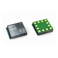
BMA250 Bosch Sensortec, BMA250 Datasheet - Page 4

BMA250
Manufacturer Part Number
BMA250
Description
3-AXIS ACCELEROMETER DIGITAL I/F
Manufacturer
Bosch Sensortec
Series
-r
Specifications of BMA250
Featured Product
BMA250 - Digital, Triaxial Acceleration Sensor
Axis
X, Y, Z
Acceleration Range
±2g, 4g, 8g, 16g
Sensitivity
256LSB/g, 128LSB/g, 64LSB/g, 16LSB/g
Voltage - Supply
1.62 V ~ 3.6 V
Output Type
I²C™, SPI™
Bandwidth
8Hz ~ 1kHz
Interface
I²C, SPI
Mounting Type
Surface Mount
Package / Case
12-VQFN
Lead Free Status / Rohs Status
Lead free / RoHS Compliant
For Use With
828-1024 - BMA250 DAUGHTERCARD FOR DEV KIT
Other names
828-1023-2
Available stocks
Company
Part Number
Manufacturer
Quantity
Price
Part Number:
BMA250
Manufacturer:
BOSCH/博世
Quantity:
20 000
Company:
Part Number:
BMA250E
Manufacturer:
AME
Quantity:
12 000
Part Number:
BMA250E
Manufacturer:
BOSCH/博世
Quantity:
20 000
Part Number:
BMA250E(F)
Manufacturer:
BOSCH/博世
Quantity:
20 000
Part Number:
BMA250E-F
Manufacturer:
BOSCH/博世
Quantity:
20 000
Company:
Part Number:
BMA250EF
Manufacturer:
TE
Quantity:
30 000
Part Number:
BMA250EF
Manufacturer:
BOSCH/博世
Quantity:
20 000
1. SPECIFICATION...................................................................................................................................... 7
2. ABSOLUTE MAXIMUM RATINGS.......................................................................................................... 9
3. BLOCK DIAGRAM................................................................................................................................. 10
4. FUNCTIONAL DESCRIPTION............................................................................................................... 10
Rev. 1.0
© Bosch Sensortec GmbH reserves all rights even in the event of industrial property rights. We reserve all rights of disposal such
as copying and passing on to third parties. BOSCH and the symbol are registered trademarks of Robert Bosch GmbH, Germany.
Note: Specifications within this document are subject to change without notice.
4.1 P
4.2 O
4.3 P
4.4 S
4.5 S
4.6 O
4.7 N
4.8 I
4.2.1 General mode............................................................................................................................. 12
4.2.2 Dedicated mode (μC-less or stand-alone mode)....................................................................... 12
4.4.1 Acceleration data ....................................................................................................................... 16
4.4.2 Temperature data....................................................................................................................... 17
4.6.1 Slow compensation .................................................................................................................... 20
4.6.2 Fast compensation..................................................................................................................... 21
4.6.3 Manual compensation ................................................................................................................ 21
4.6.4 Inline calibration ......................................................................................................................... 21
4.8.1 General features ........................................................................................................................ 23
4.8.2 Mapping (inttype to INT Pin#) .................................................................................................... 24
4.8.3 Electrical behaviour (INT pin# to open-drive or push-pull) ........................................................ 24
4.8.4 New data interrupt...................................................................................................................... 25
4.8.5 Any-motion (slope) detection ..................................................................................................... 25
4.8.5.1 Enabling (disabling) for each axis........................................................................................... 26
4.8.5.2 Axis and sign information of any motion interrupt................................................................... 26
4.8.5.3 Serial interface and dedicated wake-up mode........................................................................ 26
4.8.6 Tap sensing................................................................................................................................ 26
4.8.6.1 Single tap detection................................................................................................................. 28
4.8.6.2 Double tap detection ............................................................................................................... 28
4.8.6.3 Selecting the timing of tap detection ....................................................................................... 28
4.8.6.4 Axis and sign information of tap sensing ................................................................................ 28
4.8.6.5 Tap sensing in low power mode ............................................................................................. 29
4.8.7 Orientation recognition ............................................................................................................... 29
4.8.7.1 Orientation blocking ................................................................................................................ 32
4.8.8 Flat detection.............................................................................................................................. 33
4.8.9 Low-g interrupt ........................................................................................................................... 34
4.8.10 High-g interrupt ........................................................................................................................ 34
4.8.10.1 Axis and sign information of high-g interrupt ........................................................................ 35
NTERRUPT CONTROLLER
OWER MANAGEMENT
OWER MODES
ENSOR DATA
ELF
ON
PERATIONAL MODES
FFSET COMPENSATION
-
-
VOLATILE MEMORY
TEST
.......................................................................................................................................... 18
..................................................................................................................................... 16
.................................................................................................................................... 14
......................................................................................................................... 10
......................................................................................................................... 11
...................................................................................................................... 18
...................................................................................................................... 22
..................................................................................................................... 22
Page 4 / not for publishing
Index of Contents
Data sheet
BMA250
Bosch Sensortec
03 March 2011


