84-8511.3620 EAO, 84-8511.3620 Datasheet - Page 8
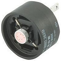
84-8511.3620
Manufacturer Part Number
84-8511.3620
Description
08N6130
Manufacturer
EAO
Datasheet
1.84-0100.0.pdf
(50 pages)
Specifications of 84-8511.3620
Contact Configuration
SPST-NO
Contact Voltage Ac Nom
42V
Contact Voltage Dc Nom
42V
Contact Current Max
20mA
Actuator Style
Round
Switch Terminals
Solder Lug
Actuator / Cap Color
Orange
Rohs Compliant
Yes


Mounting instruction
0
The arrangement of the mounting flanges and their number is determined by the size of
the front panel or PCB. To ensure uniform, tactile switching, we recommend a layout of
the flanges as per adjacent sketch.
For large PCBs with several switching elements we recommend the following procedure :
1. Fit the actuator to the front panel.
2. Clip the mounting flange to the rear of the intended actuator.
3. Screw the PCB with the components soldered to it to the assembled mounting flange.
This arrangement applies to PCBs 1.6 mm thick.
>
The tool 84-998 must be used for removing the mounting flange from the actuator. Before
removing the flange, the PCB fixing srews must be loosened.
Arrangement mounting flange for switching- and illumination element, PCB mounting
Dismantling mounting flange
6
05.2009
84
Related parts for 84-8511.3620
Image
Part Number
Description
Manufacturer
Datasheet
Request
R

Part Number:
Description:
Cap Film 260uF 400VDC PP 10% 84 X 51mm Screw Terminal Can Bulk
Manufacturer:
Kemet
Datasheet:

Part Number:
Description:
Indicator
Manufacturer:
EAO
Datasheet:


Part Number:
Description:
Switch Actuator
Manufacturer:
EAO
Datasheet:

Part Number:
Description:
Switch Actuator
Manufacturer:
EAO
Datasheet:
Part Number:
Description:
Switch Actuator
Manufacturer:
EAO
Datasheet:

Part Number:
Description:
INDICATOR, ALUMINUM
Manufacturer:
EAO
Datasheet:

Part Number:
Description:
SINGLE CHIP LED/ T1 BI-PIN/ 2.1VDC/20MA - RED
Manufacturer:
EAO
Datasheet:

Part Number:
Description:
INDICATOR, INCAND LAMP, BI PIN
Manufacturer:
EAO
Datasheet:

Part Number:
Description:
INDICATOR, BI-PIN
Manufacturer:
EAO
Datasheet:

Part Number:
Description:
INDICATOR, INCAND LAMP, MIDGET GROOVED
Manufacturer:
EAO
Datasheet: