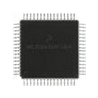
MC68HC711E9FU Freescale Semiconductor, MC68HC711E9FU Datasheet - Page 69

MC68HC711E9FU
Manufacturer Part Number
MC68HC711E9FU
Description
Manufacturer
Freescale Semiconductor
Datasheet
1.MC68HC711E9FU.pdf
(242 pages)
Specifications of MC68HC711E9FU
Cpu Family
HC11
Device Core Size
8b
Frequency (max)
4MHz
Interface Type
SCI/SPI
Program Memory Type
EPROM
Program Memory Size
12KB
Total Internal Ram Size
512Byte
# I/os (max)
38
Number Of Timers - General Purpose
8
Operating Supply Voltage (typ)
3.3/5V
Operating Supply Voltage (max)
5.5V
Operating Supply Voltage (min)
3V
On-chip Adc
8-chx8-bit
Instruction Set Architecture
CISC
Operating Temp Range
0C to 70C
Operating Temperature Classification
Commercial
Mounting
Surface Mount
Pin Count
64
Package Type
PQFP
Lead Free Status / Rohs Status
Not Compliant
Available stocks
Company
Part Number
Manufacturer
Quantity
Price
- Current page: 69 of 242
- Download datasheet (2Mb)
4.2.6.5 Interrupt Mask (I)
The interrupt request (IRQ) mask (I bit) is a global mask that disables all maskable interrupt sources.
While the I bit is set, interrupts can become pending, but the operation of the CPU continues uninterrupted
until the I bit is cleared. After any reset, the I bit is set by default and can only be cleared by a software
instruction. When an interrupt is recognized, the I bit is set after the registers are stacked, but before the
interrupt vector is fetched. After the interrupt has been serviced, a return-from-interrupt instruction is
normally executed, restoring the registers to the values that were present before the interrupt occurred.
Normally, the I bit is 0 after a return from interrupt is executed. Although the I bit can be cleared within an
interrupt service routine, "nesting" interrupts in this way should only be done when there is a clear
understanding of latency and of the arbitration mechanism. Refer to
4.2.6.6 Half Carry (H)
The H bit is set when a carry occurs between bits 3 and 4 of the arithmetic logic unit during an ADD, ABA,
or ADC instruction. Otherwise, the H bit is cleared. Half carry is used during BCD operations.
4.2.6.7 X Interrupt Mask (X)
The XIRQ mask (X) bit disables interrupts from the XIRQ pin. After any reset, X is set by default and must
be cleared by a software instruction. When an XIRQ interrupt is recognized, the X and I bits are set after
the registers are stacked, but before the interrupt vector is fetched. After the interrupt has been serviced,
an RTI instruction is normally executed, causing the registers to be restored to the values that were
present before the interrupt occurred. The X interrupt mask bit is set only by hardware (RESET or XIRQ
acknowledge). X is cleared only by program instruction (TAP, where the associated bit of A is 0; or RTI,
where bit 6 of the value loaded into the CCR from the stack has been cleared). There is no hardware
action for clearing X.
4.2.6.8 STOP Disable (S)
Setting the STOP disable (S) bit prevents the STOP instruction from putting the M68HC11 into a
low-power stop condition. If the STOP instruction is encountered by the CPU while the S bit is set, it is
treated as a no-operation (NOP) instruction, and processing continues to the next instruction. S is set by
reset; STOP is disabled by default.
4.3 Data Types
The M68HC11 CPU supports four data types:
A byte is eight bits wide and can be accessed at any byte location. A word is composed of two consecutive
bytes with the most significant byte at the lower value address. Because the M68HC11 is an 8-bit CPU,
there are no special requirements for alignment of instructions or operands.
Freescale Semiconductor
1. Bit data
2. 8-bit and 16-bit signed and unsigned integers
3. 16-bit unsigned fractions
4. 16-bit addresses
M68HC11E Family Data Sheet, Rev. 5.1
Chapter 5 Resets and
Interrupts.
Data Types
69
Related parts for MC68HC711E9FU
Image
Part Number
Description
Manufacturer
Datasheet
Request
R

Part Number:
Description:
APPENDIX A ELECTRICAL CHARACTERISTICS
Manufacturer:
FREESCALE [Freescale Semiconductor, Inc]
Datasheet:
Part Number:
Description:
Manufacturer:
Freescale Semiconductor, Inc
Datasheet:
Part Number:
Description:
Manufacturer:
Freescale Semiconductor, Inc
Datasheet:
Part Number:
Description:
Manufacturer:
Freescale Semiconductor, Inc
Datasheet:
Part Number:
Description:
Manufacturer:
Freescale Semiconductor, Inc
Datasheet:
Part Number:
Description:
Manufacturer:
Freescale Semiconductor, Inc
Datasheet:
Part Number:
Description:
Manufacturer:
Freescale Semiconductor, Inc
Datasheet:
Part Number:
Description:
Manufacturer:
Freescale Semiconductor, Inc
Datasheet:
Part Number:
Description:
Manufacturer:
Freescale Semiconductor, Inc
Datasheet:
Part Number:
Description:
Manufacturer:
Freescale Semiconductor, Inc
Datasheet:
Part Number:
Description:
Manufacturer:
Freescale Semiconductor, Inc
Datasheet:
Part Number:
Description:
Manufacturer:
Freescale Semiconductor, Inc
Datasheet:
Part Number:
Description:
Manufacturer:
Freescale Semiconductor, Inc
Datasheet:
Part Number:
Description:
Manufacturer:
Freescale Semiconductor, Inc
Datasheet:
Part Number:
Description:
Manufacturer:
Freescale Semiconductor, Inc
Datasheet:


