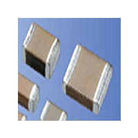
CM05CG1R2B50AH AVX Corporation, CM05CG1R2B50AH Datasheet - Page 16

CM05CG1R2B50AH
Manufacturer Part Number
CM05CG1R2B50AH
Description
Manufacturer
AVX Corporation
Datasheet
1.CM05CG1R2B50AH.pdf
(16 pages)
Specifications of CM05CG1R2B50AH
Capacitance
1.2pF
Tolerance (+ Or -)
0.1pF
Voltage
50VDC
Temp Coeff (dielectric)
C0G
Operating Temp Range
-55C to 125C
Mounting Style
Surface Mount
Package / Case
0402
Construction
SMT Chip
Case Style
Ceramic Chip
Failure Rate
Not Required
Wire Form
Not Required
Product Length (mm)
1mm
Product Depth (mm)
0.5mm
Product Height (mm)
0.55mm
Product Diameter (mm)
Not Requiredmm
Lead Free Status / Rohs Status
Compliant
Multilayer Ceramic Chip Capacitors
Surface Mounting Information
Soldering Method
1) Ceramic is easily damaged by rapid heating or cooling. If some heat shock is unavoidable, preheat enough to limit the temperature difference
2) The product size 1.0×0.5mm to 3.2×1.6mm can be used in reflow and wave soldering, and the product size of over 3.2×2.5mm, 0.6×0.3mm,
3) Please see our recommended soldering conditions.
Sodering iron
1) Temperature of iron chip
2) Wattage
3) Tip shape of soldering iron
4) Soldering Time
Reflow
Wave
① Ensure that the chip capacitor is preheated adequately.
② Ensure that the temperature difference (T) does not exceed 150°C.
③ Cool naturally after soldering.
④ Wave soldering is not applicable for chips with size of 3.2x2.5mm or larger.
① Minimize soldering time.
② Ensure that allowable temperature difference does not exceed 150°C.
③ Ensure that allowable temperature difference does not exceed 130°C for 3.22.5mm size or larger.
(Delta T) to within 130 degree Celsius.
and capacitor arrays can be used in reflow.
Circuit shortage and smoking can be created by using capacitors which are used neglecting the above caution.
300
250
200
150
100
300
250
200
150
100
50
50
Recommended Temperature Profile (62Sn Solder)
0
0
60 seconds
60 to 120 sec.
Preheat
Preheat
60 seconds
380°C max.
80W max.
φ3.0mm max.
3 sec. max.
T
T
More than180°C,
40 seconds maximum
5 sec. max.
Peak temperature
230°C5°C
15 seconds maximum
Cool at normal
room temperature
Cool at normal room
temperature after
removing from
5) Cautions
furnace.
a) Pre−heating is necessary Rapid heating must be avoided.
b) Avoid direct touching to capacitors.
c) Avoid rapid cooling after soldering. Natural cooling is recommended.
Delta T≤150°C
Reflow
Wave
① Minimize soldering time.
② Ensure that allowable temperature difference does not exceed 150°C.
③ Ensure that allowable temperature difference does not exceed 130°C for 3.22.5mm size or larger.
① Ensure that the chip capacitor is preheated adequately.
② Ensure that the temperature difference (T) does not exceed 150°C.
③ Cool naturally after soldering.
④ Wave soldering is not applicabel for chips with size of 3.2�2.5mm or larger.
Recommended Temperature Profile (Sn−3Ag−0.5Cu)
300
250
200
150
100
300
250
200
150
100
50
0
1 to 3°C/ sec.
60 to 120 sec.
Preheat
Preheat
170 to 180°C
9030 sec.
T
5 sec. max.
250°C5°C
5 to 10 sec. max.
90 sec. max.
220°C max.
Cool at normal
room temperature


