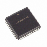
DS2151QNB Maxim Integrated Products, DS2151QNB Datasheet - Page 17

DS2151QNB
Manufacturer Part Number
DS2151QNB
Description
IC TXRX T1 1-CH 5V LP IND 44PLCC
Manufacturer
Maxim Integrated Products
Datasheet
1.DS2151QB.pdf
(60 pages)
Specifications of DS2151QNB
Function
Single-Chip Transceiver
Interface
T1
Number Of Circuits
1
Voltage - Supply
4.75 V ~ 5.25 V
Current - Supply
65mA
Operating Temperature
-40°C ~ 85°C
Mounting Type
Surface Mount
Package / Case
44-LCC, 44-PLCC
Includes
Alarm Detector and Generator, CSU Loop Codes Generator and Detector, DSX-1 and CSU Line Build-Outs Generator
Lead Free Status / RoHS Status
Contains lead / RoHS non-compliant
Power (watts)
-
CCR3: COMMON CONTROL REGISTER 3 (Address = 30 Hex)
ESMDM
(MSB)
SYMBOL
ESMDM
LIRST
RSMS
P16F
PDE
TLD
TLU
ESR
ESR
POSITION
CCR3.7
CCR3.6
CCR3.5
CCR3.4
CCR3.3
CCR3.2
CCR3.1
CCR3.0
P16F
NAME AND DESCRIPTION
Elastic Store Minimum Delay Mode. See Section
details.
0=elastic stores operate at full two-frame depth
1=elastic stores operate at 32-bit depth
Elastic Store Reset. Setting this bit from a 0 to a 1 will force
the elastic stores to a known depth. Should be toggled after
SYSCLK has been applied and is stable. Must be cleared and
set again for a subsequent reset.
Function of Pin 16.
0 = Receive Loss of Sync (RLOS).
1 = Loss of Transmit Clock (LOTC).
RSYNC Multiframe Skip Control. Useful in framing format
conversions from D4 to ESF.
0 = RSYNC will output a pulse at every multiframe
1 = RSYNC will output a pulse at every other multiframe note:
for this bit to have any affect, the RSYNC must be set to output
multiframe pulses (RCR2.4 = 1 and RCR2.3 = 0) and the
receive elastic store must be bypassed. (CCR1.2 = 0).
Pulse Density Enforcer Enable.
0 = disable transmit pulse density enforcer
1 = enable transmit pulse density enforcer
Transmit Loop Down Code (001).
0 = transmit data normally
1 = replace normal transmitted data with Loop Down code
Transmit Loop Up Code (00001).
0 = transmit data normally
1 = replace normal transmitted data with Loop Up code
Line Interface Reset. Setting this bit from a 0 to a one will
initiate an internal reset that affects the slicer, AGC, clock
recovery state machine and jitter attenuator. Normally this bit is
only toggled on power-up. Must be cleared and set again for a
subsequent reset.
RSMS
17 of 60
PDE
TLD
TLU
LIRST
(LSB)
11
for


